background image

14


T

h

e d

at

a a

n

d i

n

fo

rm

at

io

n p

rovi

d

ed

 i

n

 t

h

is

 m

an

u

al

 a

re to b

e c

o

n

si

d

er

ed

 s

u

sc

ep

ti

b

le to c

h

an

g

e a

t a

n

y t

im

e w

it

h

o

u

t w

ar

n

in

g

, by CAM

E c

an

ce

ll

i a

u

to

m

at

ic

i S

.p

.A

.

ENGLISH

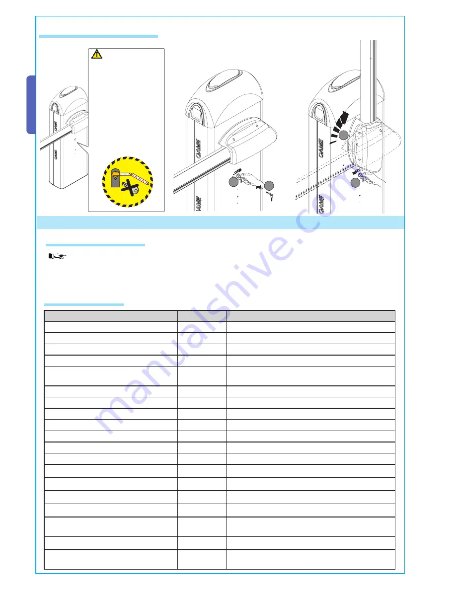
      WARNING! The release 
procedure may constitute a 
hazard for the user when, 
for whatever reason – the 
bar is fixed improperly to 
the housing during assem-
bly, or the bar is cracked or 
broken in an accident, and 
so on – the tension springs 
no longer provide balance! 
These can thus cause a 
brusque rotation of the bar 
attachment and/or of the 
bar itself.

5.9 Manual release of the barrier

MALFUNCTIONS

REFERENCES

CHECKS

The unit neither opens nor shuts

1-2-3-4-6-8-20 1 - Chiudere sportello d’ispezione con la chiave 

The unit opens but does not close

4-7-10

2 - Disable “steady movement” with dipswitch

The unit shuts but does not open

7-9

3 – Check power supply and fuses

No automatic closure

11-12-13

4 - N.C. safety contacts open (1-2 / 2-C1)

The unit does not work if the remote control 
is used

2-14-16

6 - Disable master-slave function

The unit inverts direction

7

7 – Check spring tension and balancing

The unit works only with remote control

22

8 – Disable obstacle detection with dipswitch

The photoelectric cell does not react

12-23-24

9 – Check if end stop opens

The signalling LED indicator flashes rapidly

4

10 – Check if end stop closes

The signalling LED indicator remains on

13

11 - Activate “automatic closure” dip switch

The unit does not end its run

7

12 – Check the correct direction of movement

The bar is not properly balanced

7-15

13 - (2-3 / 2-4 / 2-7) command button

14 -Check jumper on AF43S, turn on/off power

15 – Check the bar length ratio with mountable accessories

16 – Re-save radio code

20 - Raise the motor torque

22 - Enter or duplicate the same code in all the remote 
controls

23 - Activate the photoelectric cell with the dipswitch

24 - Connect the photoelectric cells in a series, not in 
parallel

6.1 Periodic maintenance


The unit does not require specifi c maintenance. Only as a precautionary measure and in case of intensive use, we re-

commend periodic checks (every 6 months) on the state of the electric wire connected to the motor, the spring-bar balance, the 
tightness of the nuts and the proper oiling of the sliding points between fi xed and mobile parts.

All checks must be recorded (in a dedicated record-book).

6 Maintenance

6.2 Problem solving

- Manually raise the bar 
and block it again by 
turning the key counter-
clockwise.

- Insert the key into the lock and 
turn it clockwise.

Содержание GARD 8 SERIES

Страница 1: ...G2081 G2081I AUTOMATION FOR STREET BARRIERS INSTALLATION MANUAL GARD 8 SERIES ...

Страница 2: ...bligatory for accesses of over 3 6m 003 ZG5 Electric board designed to accommodate radio board coupling 003 ZG6 Electric board designed to accommodate radio board coupling The following accessories are optional to the GARD 8 automation system 002 RSE Board for combined battery operation control and or compass for ZG5 control board 001 G02801 Flashing dome lamp 001 G02802 Support for mounting the p...

Страница 3: ...Parts description AUTOMATION UNIT ACCESSORIES VIEW FROM THE BAR SUPPORT BRACKET VIEW FROM INSPECTION HATCH 1 G02000 G04000 aluminium bar painted white Ø 100 mm 2 G02040 Ø40 yellow balancing spring 3 G04060 Ø50 green balancing spring 4 G06080 Ø55 red balancing spring 5 G02806 Rack 6 G02802 Support for DIR photoelectric cells 7 G02803 Luminous cord 8 G02807 Fixed barrier support 9 G02808 Mobile barr...

Страница 4: ...ctions inside the case made for protection circuit continuity are allowed as long as they include additional insulation with respect to other internal drive parts Install suitable tubes and ducts for electric cable passage to guarantee protection against mechanical damage Installation must be carried out by expert qualified personnel and in full observance of regulations in force 5 Installation 5 ...

Страница 5: ...cable 10 20 m Length of cable 20 30 m 230V 2F power supply FROR CEI 20 22 CEI EN 50267 2 1 3G x 1 5 mm2 3G x 2 5 mm2 3G x 4 mm2 230V motor power supply 3 x 1 mm2 3 x 1 5 mm2 3 x 2 5 mm2 Photoelectric cells TX 2 x 0 5 mm2 2 x 0 5 mm2 2 x 0 5 mm2 Photoelectric cells RX 4 x 0 5 mm2 4 x 0 5 mm2 4 x 0 5 mm2 24V power supply accessory 2 x 0 5 mm2 2 x 0 5 mm2 2 x 1 mm2 Control button 2 x 0 5 mm2 2 x 0 5 ...

Страница 6: ...ole to house the fixing base and prepare sheath tubes from the branch pit for the connections Remove the nuts and washers from the threaded screws position the cabinet on the base in correspondence with the 4 threaded screws and secure with the nuts and washers Note We recommend installing the cabinet with the inspection hatch facing the internal area Fill the hole with concrete and immerge the cl...

Страница 7: ...ed Proceed in the following manner remove the spring securing bracket and the transmission rod from the lever arm loosen the motor support grub screw rotate the lever arm by 90 Fix the spring securing bracket and the transmission rod on the side opposite that of lever arm tighten the grub screw invert the motor s U V phases and the FA and FC endstop wires on the control panel terminal 5 5 Installa...

Страница 8: ...ion the middle plate between the fitting plate and the bar fitting cover and put in one UNI 5931 M8x20 screw without tightening it to facilitate bar assembly Insert it in the bar s conduit a procedure that should be carried out on both sides Insert the shock resistant profile and cut excess length Lastly secure the bar end plug with the screws provided Insert the bar in the fitting cover and secur...

Страница 9: ...re bar rack Bare bar rack luminous cord Passage clearance lamp m 2 2 5 3 3 5 4 4 5 5 5 5 6 6 5 7 7 6 By Bare bar we mean a bar complete with the transparent slot cover and end plug 400 mm Prior to bar balancing select a suitable spring depending on the situation at hand See table below Tighten the anti shearing protection cover to the bar fitting with UNI6954 Ø3 9x19 screws 5 6 Bar balancing PASSA...

Страница 10: ...Release the gearmotor and position the bar vertically and then refasten the gearmotor Hook the tie rod to the anchoring racket Perform the same procedure if there is a second screw Insert the UNI5739 M12X70 screw into the spring securing bracket and tighten the UNI5588 M12 nut to the screw 1 2 Tighten the screw to spring 2 and the tie rod to the part underneath 3 4 ...

Страница 11: ...d refasten the gearmotor Note make sure the spring functions properly the spring is loose when the bar is in the vertical position at rest the spring is tight when the bar is in the horizontal position tense 5 7 Electric board installation Loosen the three screws in the container cover located in the upper part of the unit Insert the board in the container and fasten it with the screws provided ca...

Страница 12: ...ard carry out a series of steps to make sure of the bar s correct opening and closing positions and then if necessary proceed to the adjustment of the dampers Warning For greater safety and better unit performance the bar s opening and closing operations should be carried out with the inspection hatch closed Execute the closing operation adjust the open bar s position by turning the free damper cl...

Страница 13: ...g by CAME cancelli automatici S p A ENGLISH place back the inspection door 1 and the upper dome 2 Lock the door with the key After bar opening and closing adjustment tighten the locking nuts under the dampers After making adjustments and settings from the control panel put the container lid in place and secure with screws ...

Страница 14: ...detection with dipswitch The photoelectric cell does not react 12 23 24 9 Check if end stop opens The signalling LED indicator flashes rapidly 4 10 Check if end stop closes The signalling LED indicator remains on 13 11 Activate automatic closure dip switch The unit does not end its run 7 12 Check the correct direction of movement The bar is not properly balanced 7 15 13 2 3 2 4 2 7 command button ...

Страница 15: ...should therefore be removed and given to qualified service companies for proper disposal Prior to disposal it is always advisable to check specific regulations in force in the place of disposal PLEASE DISPOSE OF PROPERLY 7 Demolition and disposal MANUFACTURER S DECLARATION OF CONFORMITY Pursuant to annex II B of the Machinery Directive 98 37 EC CAME Cancelli Automatici S p A via Martiri della Libe...

Страница 16: ...Cod 119GT41 ver 1 0 06 06 CAME CANCELLI AUTOMATICI ...

Отзывы: