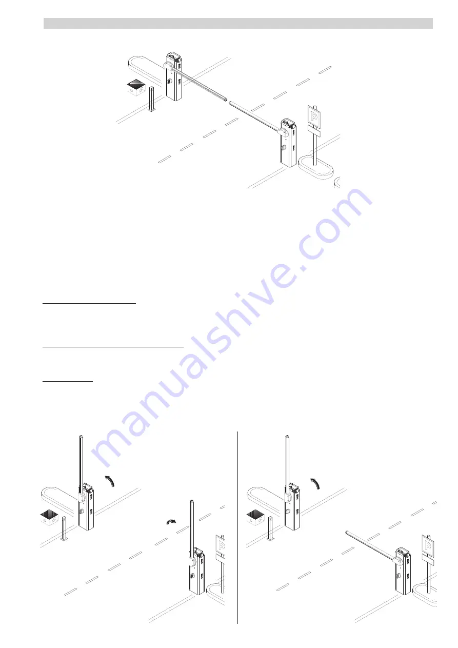
MASTER
SLAVE
MASTER
SLAVE
MASTER
SLAVE
p.
2
7
27
- M
an
u
al
c
od
e:
F
A
0
1
2
8
3
-E
N
FA
0
1
2
8
3
-E
N
v.
11
- 1
1/
2
0
18 - © C
am
e S
.p.
A
. - T
h
e m
an
u
al
's c
onte
nts m
ay b
e e
d
ite
d at a
ny ti
m
e w
ith
ou
t n
oti
ce
.
Important! Before making any electrical connections and programming, do the following on both barriers:
- setting the boom type;
- motor test;
- calibrating the boom travel.
Fit the RSE card (with DIP switches sent to OFF) onto the control panel connector of both barriers.
Connect the two control panels via a CAT 5 type-cable (max 1,000 m) to terminals A-A / B-B / GND-GND, see paragraph on CONNECTING WITH
THE CAME REMOTE PROTOCOL (CRP) AND FOR PAIRED OR ALTERNATE OPERATING MODE. Connect all of the control and safety devices to the
MASTER control panel.
Important! Deactivate function F 19 (automatic closing time) on the SLAVE barrier's control panel.
Confi guring the MASTER barrier
Select function F 49. Press ENTER to confi rm.
Select 1 (paired) and press ENTER.
Carry out any settings and adjustments on the MASTER control panel.
Transferring parameters from MASTER to SLAVE
Select function F 52 on the MASTER control panel.
Select 1 and press ENTER.
Operating modes
STEP-STEP or OPEN ONLY command. Both booms open.
PARTIAL OPENING/PEDESTRIAN command. Only the MASTER barrier opens.
For the types of command that can be selected and paired to users, see the ENTERING USERS WITH ASSOCIATED COMMANDS
PAIRED CONNECTION


