

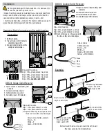

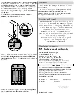


Dip-switch function
Dip 1 ON
= photo diode 1 is active
Dip 2 ON
= photo diode 2 is active
A single function may be assigned even if
there are two safety sensitive edges
24V
0
TS
C
NC
2
1
ON
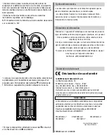
Dip-switch function
Dip 1 ON = photo diode 1 is active
Dip 2 ON = photo diode 2 is active
Different functions can be assigned to
the two safety sensitive edges
24V
0
TS
C
NC
2
1
ON
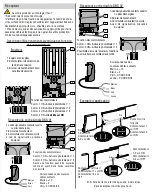
Colour codes
Cables-contacts
Brown = 10
White = 2
Green = C1/C2/C3/C4
Yellow = C1/C2/C3/C4
Note: should the door close toward the left, invert
the two examples illustrated above.
Example.
K
K
K
K
K
R13
R15
R22
R23
4
3
2
1
2
1
Contact on yellow cable
Dip 1 set at OFF
Dip 2 set at ON
K
K
K
K
R13
R15
R23
4
3
2
1
2
1
Dip 1-2 set at OFF
Dip 3-4 set at ON
Contact on green cable
Dip 1 set at ON
Dip 2 set at OFF
Dip 1-2 set at ON
Dip 3-4 set at OFF
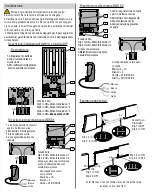
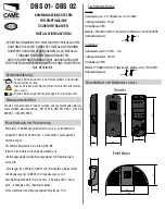
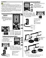
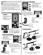
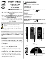
Transmitter
Description/Electric Connections and Dip-switch functions
1 2 3 4 5 6 7 8 9 10 11 12
05 06 07 08 09 V1 V2 V3
1,5V AAA
+
-
+
-
-
+
-
+
1,5V AAA
K
K
K
R13
R15
R22
R23
1
+
-
+
-
-
+
+
-
3
2
1- Battery lodging
2- Transmission LED indicator
selection dip-switch
3- Connection terminal board for
safety sensitive edges
4
3
2
1
K
K
K
R13
R15
R22
R23
ON
Dip-switch functions
Dip 1 ON = photo diode 1 is active
Dip 2 ON = photo diode 2 is active
Dip 3 ON = photo diode 3 is active
Dip 4 ON =
must be set to ON
1- Open contacts or dead battery LED
indicator
2- Connection terminal board
3- Outlet selection dip-switch
4- Activated signal LED indicator
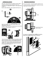
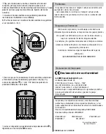
DBS 01 Single Outlet Receiver
Colour codes Cables-contacts
Brown = 10
White = 2
Green = C1/C2/C3/C4
1
2
3
4
24V
24V
0
0
TS
TS
C
C
NC
NC
#
Green
White
Brown
DBS 02 Double Outlet Receiver
1
2
3
4
24V
24V
0
0
TS
TS
C
C
NC
NC
##
1- Open contacts or dead battery LED
indicator
2- Connection terminal board
3- Outlet selection dip-switch
4- Activated signal LED indicator
Brown
White
Green
Yellow
TX
RX
RX
TX
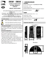
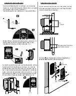
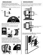
Before proceeding with the installation, it is necessary to:
• make sure that the mains power is off.
• Check that the product is installed in an area protected from
bumps and that the anchorage surface is solid, and that it is
secured with suitable elements (screws, inserts, etc).
• Install suitable tubes and ducts for electric cable passage to
guarantee protection against mechanical damage.
Installation


