CAME DBS01 Скачать руководство пользователя страница 23

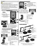
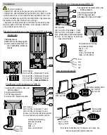
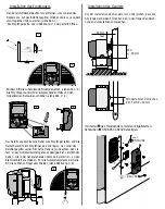
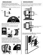
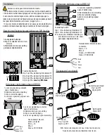
Installatie van de ontvanger

Verwijder het plastic deksel van de motor, druk vanaf de 
binnenkant van het deksel op het verluchtingsrooster om dit uit 
zijn oorspronkelijke invoegplaats los te krijgen, zoals afgebeeld 
in fi guur 1.
Open de ontvangerskaart, zoals afgebeeld in fi guur 2.

Selecteer via de dip switches welke fotodiode u wenst te 
gebruiken, zoals afgebeeld in fi guur 3.
Sluit de ontvangerskaart met de bijbehorende koker en de 
bijgeleverde schroeven, zoals afgebeeld in fi guur 4.

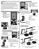
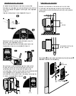
Breng de reeds op de ontvanger aangesloten kabel er door 
en plaats de halve maan met de ontvanger, daar waar het 
verluchtingsrooster ligt, en bevestig hem goed aan de 
automatisatiekast. Sluit tot slot de kabel aan op het klemmenbord 
zoals uitgelegd wordt in de kolom hiernaast 4. Voor 
automatisaties uit de serie BZ moet u de spietjes op de zijkant er 
af snijden,  zoals afgebeeld in fi guur 5.

24V

0

0

TS

TS

C

NC

2

1

643#.#

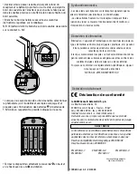
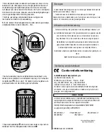
Installatie van de zender

1

2

24V

0

0

TS

TS

C

NC

2

1

643#.#

24V

0

0

TS

TS

C

NC

2

1

643#.#

3

24V

0

TS

C

C

NC

NC

2

1

#.#

4

5

Alvorens de installatie van de zender aan te vatten moet 
u controleren dat de afstanden tussen de twee fotocellen 
overeenstemmen met de afmetingen vermeld op de volgende 
tekeningen.

• De bodem   van de zender vastzetten met de schroeven   
UNI 6954 3.9x32 in de verpakking.

30 mm 

max

150
+/- 30 mm

minimumafstand tussen
TX-RX = 30 mm

Содержание DBS01

Страница 1: ...tto in oggetto sono state considerate le seguenti nor mative di riferimento EN 12978 UNI EN 954 1 CEI EN 60335 1 UNI EN 12453 ISTRUZIONI IMPORTANTI PER LA SICUREZZA DURANTE L INSTALLAZIONE ATTENZIONE...

Страница 2: ...sicurezza 4 3 2 1 K K K R13 R15 R22 R23 ON Funzione Dip Dip 1 in ON Attivo foto diodo n 1 Dip 2 in ON Attivo foto diodo n 2 Dip 3 in ON Attivo foto diodo n 3 Dip 4 in ON deve essere in ON 1 Led di se...

Страница 3: ...a con il ricevitore dove era ubicata la griglia di aereazione facendola agganciare bene alla cassa dell automatismo in fine collegare il cavo sulla morsettiera come spiegato nella colonna affianco 4 P...

Страница 4: ...l luogo di smaltimento NON DISPERDERE NELL AMBIENTE K K K 1 2 3 4 5 6 7 8 9 10 11 12 1 2 3 4 5 6 7 8 9 10 11 12 05 06 07 08 09 V1 V2 V3 05 06 07 08 09 V1 V2 V3 1 5V AAA 1 5V AAA 1 5V AAA 1 5V AAA R13...

Страница 5: ...nterlocked relay contact with single outlet DBS02 with double outlet with connections available for testing operations 2 active channel LED indicators 2 dead battery LED indicators Maximum distance tr...

Страница 6: ...ion LED indicator selection dip switch 3 Connectionterminalboardfor safety sensitive edges 4 3 2 1 K K K R13 R15 R22 R23 ON Dip switch functions Dip 1 ON photo diode 1 is active Dip 2 ON photo diode 2...

Страница 7: ...with the Receiver where the aeration grid was located hooking it to the automatic system s case and then connect the cable to the terminal board as instructed in column 4 For BZ series automatic syste...

Страница 8: ...tions in force in the place of disposal PLEASE DISPOSE OF PROPERLY K K K 1 2 3 4 5 6 7 8 9 10 11 12 1 2 3 4 5 6 7 8 9 10 11 12 05 06 07 08 09 V1 V2 V3 05 06 07 08 09 V1 V2 V3 1 5V AAA 1 5V AAA 1 5V AA...

Страница 9: ...ndant sortie simple DBS02 sortie double avec possibilit de branchement pour le test des services 2 leds de signalisation canal actif 2 leds de signalisation piles d charg es Distance maximale metteur...

Страница 10: ...ateur de s lection du led de transmission 3 Bornier de branchement bord sensible de s curit 4 3 2 1 K K K R13 R15 R22 R23 ON Fonction des commutateurs Comm 1 ON Active la photodiode n 1 Comm 2 ON Acti...

Страница 11: ...pteur et placer la demi lune avec le r cepteur o se trouvait la grille d a ration en l accrochant bien au bo tier de l automatisme Brancher ensuite le c ble au bornier comme sur la colonne 4 ci contre...

Страница 12: ...6 2 EN 61000 6 3 EN 60335 1 EN 13241 1 DBS01 DBS02 K K K 1 2 3 4 5 6 7 8 9 10 11 12 1 2 3 4 5 6 7 8 9 10 11 12 05 06 07 08 09 V1 V2 V3 05 06 07 08 09 V1 V2 V3 1 5V AAA 1 5V AAA 1 5V AAA 1 5V AAA R13...

Страница 13: ...ang mit Anschlu m glichkeit f r Service Test 2 Anzeige LEDs Kanal aktiv 2 Anzeige LEDs Batterie entladen H chstabstand Uebertragungsgeraet Empf nger 10 m Beschreibung der Vorrichtung Raumbedarf und Ma...

Страница 14: ...lemmenbrett f r die empfindliche Sicherhei tskante 4 3 2 1 K K K R13 R15 R22 R23 ON DIP Funktion Dip 1 auf ON Fotodiode n 1 aktiv Dip 2 auf ON Fotodiode n 2 aktiv Dip 3 auf ON Fotodiode n 3 aktiv Dip...

Страница 15: ...ftungsgitter seinen Sitz hatte Dabei ist zu beachten da sie fest an das Automatiksystemgeh use gekuppelt ist Letztlich das Kabel wie in der nebenstehenden Kolonne 4 erkl rt ist an das Klemmenbrett ans...

Страница 16: ...6 2 EN 61000 6 3 EN 60335 1 EN 13241 1 DIW01 DIW02 K K K 1 2 3 4 5 6 7 8 9 10 11 12 1 2 3 4 5 6 7 8 9 10 11 12 05 06 07 08 09 V1 V2 V3 05 06 07 08 09 V1 V2 V3 1 5V AAA 1 5V AAA 1 5V AAA 1 5V AAA R13 R...

Страница 17: ...02 con dos salidas con la posibilidad de conexi n para los test de servicio 2 LEDs de se alizaci n de canal activo 2 leds de se alizaci n de bater a agotada Distancia m xima Transmisor Receptor 10 m E...

Страница 18: ...e seguridad 4 3 2 1 K K K R13 R15 R22 R23 ON Funci n Dip Dip 1 en ON Activa fotodiodo n 1 Dip 2 en ON Activa fotodiodo n 2 Dip 3 en ON Activa fotodiodo n 3 Dip 4 en ON debe estar en ON 1 Leddese aliza...

Страница 19: ...onde estaba colocada la rejilla de ventilaci n enganch ndola bien a la caja de la automatizaci n por ltimo conecte el cable a la regleta de conexi n tal como explicado en la columna de aqu al lado 4 P...

Страница 20: ...7 CE EN 61000 6 1 EN 61000 6 2 EN 61000 6 3 EN 60335 1 EN 13241 1 DBS01 DBS02 K K K 1 2 3 4 5 6 7 8 9 10 11 12 1 2 3 4 5 6 7 8 9 10 11 12 05 06 07 08 09 V1 V2 V3 05 06 07 08 09 V1 V2 V3 1 5V AAA 1 5V...

Страница 21: ...dubbele uitgang met mogelijkheid voor aansluiting diensttesten 2 leds voor signalering kanaal actief 2 leds voor signalering batterij leeg Maximumafstand Zender Ontvanger 10 m Voor het betreffende pro...

Страница 22: ...ibbe 4 3 2 1 K K K R13 R15 R22 R23 ON Functie Dip Switch Dip 1 op ON Activering fotodiode n 1 Dip 2 op ON Activering fotodiode n 2 Dip 3 op ON Activering fotodiode n 3 Dip 4 op ON moet op ON staan 1 L...

Страница 23: ...de ontvanger daar waar het verluchtingsrooster ligt en bevestig hem goed aan de automatisatiekast Sluit tot slot de kabel aan op het klemmenbord zoals uitgelegd wordt in de kolom hiernaast 4 Voor aut...

Страница 24: ...41 1 DBS01 DBS02 K K K 1 2 3 4 5 6 7 8 9 10 11 12 1 2 3 4 5 6 7 8 9 10 11 12 05 06 07 08 09 V1 V2 V3 05 06 07 08 09 V1 V2 V3 1 5V AAA 1 5V AAA 1 5V AAA 1 5V AAA R13 R13 R15 R15 R22 R22 R23 R23 6 6 6 6...

Отзывы: