CAME BX10 Скачать руководство пользователя страница 3

p.


3

 - M

anu

al 

FA

0

1

1

3

7

-E

N

 - 0

4

/2

0

18 - © C

A

M

E S

.p

.A

. - T

ransla

te

d o

riginal inst

ru

ct

io

ns

General precautions for installers

⚠ 

WARNING! Important safety instructions.

Follow all of these instructions. Improper installation can cause serious bodily harm.

Before continuing, also read the general precautions for users.

This product must only be used for its specifi cally intended purpose. Any other use may be hazardous. Cames s.P.A. Is not liable 
for any damage caused by improper, wrongful and unreasonable use. • This manual's product is defi ned by machinery directive 
2006/42/ce as "partly-completed machinery". Partly-completed machinery is a set that almost constitutes a machine, but which, 
alone, cannot ensure a clearly defi ned application. Partly-completed machinery is only destined to be incorporated or assembled 
to other machinery or other partly-completed machinery or apparatuses to build machinery that is regulated by directive 2006/42/
ce. The fi nal installation must comply with european directive 2006/42/ce and european reference standards: en 13241-1, en 
12453, en 12445 and en 12635 • given these considerations, all procedures stated in this manual must be exclusively performed 
by expert, qualifi ed staff  • the manufacturer declines any liability for using non-original products; which would result in warranty 
loss • keep this manual inside the technical folder along with the manuals of all the other devices used for your automation system 
• check that the operator's specifi ed temperature range suits the locations where it will be installed • laying the cables, installation 
and testing must follow state-of-the-art procedures as dictated by regulations • if the power-supply cable is damaged, replace it 
immediately through the manufacturer or an authorized technical assistance center, or qualifi ed staff , to prevent any risk • make 
sure the mains power supply is disconnected during all installation procedures • the operator cannot be used with gates fi tted with 
pedestrian doors, unless its operation can be activated only when the pedestrian door is in safety position • make sure that people 
are not entrapped between the gate's moving and fi xed parts due to the gate's movement • before installing the operator, check 
that the gate is in proper mechanical condition, that it is properly balanced and that it properly closes: if any of these conditions 
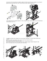
are not met, do not continue before having met all safety requirements • make sure the gate is stable and the carriage function 
properly and are well-greased, and that it opens and closes smoothly • the guide rail must be well-fastened to the ground, entirely 
above the surface and free of any impediments to the gate's movement. • The rails of the upper guide must not cause any friction 
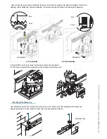
• make sure that opening and closing limiters are fi tted • make sure the operator is installed onto a sturdy surface that is protected 
from any collisions • make sure that mechanical stops are already installed. • If the operator is installed lower than 2.5 From the 
ground or from any other access level, fi t protections and signs to prevent hazardous situations • do not fi t the operator upside 
down or onto elements that could yield under its weight if necessary, add reinforcements to the fastening points • do not install 
door or gate leaves on tilted surfaces • check that no lawn watering devices spray the operator with water from the bottom up • 
any residual risks must be indicated clearly with proper signage affi  xed in visible areas. All of which must be explained to end users. 
• Suitably section off  and demarcate the entire installation site to prevent unauthorized persons from entering the area, especially 
minors and children • fi t cautionary signs, such as the gate plate, wherever needed and in plain sight • use proper protections 
to prevent mechanical hazards when people are loitering around the machinery's range of action, for example, to prevent fi nger 
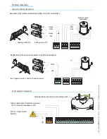
crushing between the rack and pinion) • the electrical cables must run through the cable glands and must not touch any heated 
parts, such as the motor, transformer, and so on) • make sure you have set up a suitable dual pole cut off  device along the power 
supply that is compliant with the installation rules. It should completely cut off  the power supply according to category iii surcharge 
conditions • all opening controls must be installed at least 1.85 M from the perimeter of the gate's working area, or where they 
cannot be reached from outside the gate • all switches in maintained-action mode must be positioned so that the moving gates 
leaves, the transit areas and vehicle thru-ways are completely visible, and yet the switches must be also away from any moving 
parts. • Unless the action is key operated, the control devices must be fi tted at, at least, 1.5 M from the ground and unreachable 
by any unauthorized persons. • To pass the collision force test use a suitable sensitive safety-edge. Install it properly and adjust as 
needed. • Before handing over to users, check that the system is compliant with the 2006/42/ce uniformed machinery directive. 
• Make sure the settings on the operator are all suitable and that any safety and protection devices, and also the manual release, 
work properly. • Affi  x a permanent tag, that describes how to use the manual release mechanism, close to the mechanism. • Make 
sure to hand over to the end user, all operating manuals for the products that make up the fi nal machinery.
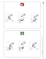
- T

HE


NEXT


FIGURE


SHOWS


THE


MAIN


HAZARD


POINTS


FOR


PEOPLE

 -

Содержание BX10

Страница 1: ...Sliding gate operator BX series BX 10 INSTALLATION MANUAL EN English FA01137 EN ...

Страница 2: ... p 2 Manual FA01137 EN 04 2018 CAME S p A Translated original instructions ...

Страница 3: ...ree of any impediments to the gate s movement The rails of the upper guide must not cause any friction make sure that opening and closing limiters are fitted make sure the operator is installed onto a sturdy surface that is protected from any collisions make sure that mechanical stops are already installed If the operator is installed lower than 2 5 From the ground or from any other access level fit...

Страница 4: ...50 60Hz Operator power supply 230V A C Draw 2 4A Power 300 W Reduction ratio 1 33 Thrust 800 N Max speed 10 m min max Duty cycle 30 Protection rating IP54 Insulation class I Motor s thermo protection 150 Weight 15 kg Intended use Legend of symbols This symbol tells you to read the section with particular care This symbol tells you that the sections concern safety issues This symbol tells you what ...

Страница 5: ...cts Make sure you have a suitable omnipolar cut off device with contacts more than 3 mm apart and independent sectioned off power supply Check that any connections inside the container that provide continuity to the safety circuit are fitted with additional insulation compared to other internal live parts Make sure you have suitable tubing and conduits for the electrical cables to pass through and...

Страница 6: ... of cable 10 20 m Length of cable 20 30 m Control panel power supply 230V FROR CEI 20 22 CEI EN 50267 2 1 3G x 1 5 mm2 3G x 2 5 mm2 3G x 4 mm2 Flashing light 2 x 0 5 mm2 2 x 1 mm2 2 x 1 5 mm2 Photocell transmitter 2 x 0 5 mm2 2 x 0 5 mm2 2 x 0 5 mm2 Photocell receiver 4 x 0 5 mm2 4 x 0 5 mm2 4 x 0 5 mm2 Accessories power supply 2 x 0 5 mm2 2 x 0 5 mm2 2 x 1 mm2 Safety and control devices 2 x 0 5 m...

Страница 7: ...e solution Shunt pit Conduits for electric cables Prepare the securing plate insert the bolts into the holes and lock them using the supplied nuts and washers Extract the preformed brackets using a screw driver or a set of pliers Position the plate on top of the grid Careful The tubes need to pass through the apposite holes Prepare a form box that is larger in size than the securing plate and inse...

Страница 8: ...solidify Remove the form box fill the pit around the cement block with soil Unbolt the nuts and washers from the bolts The securing plate must be clean perfectly aligned and with the bolt threads completely on the surface Insert the electric cables into the tubes until they exit about 400mm p 8 Manual FA01137 EN 04 2018 CAME S p A Translated original instructions ...

Страница 9: ...pinion and the rack The following illustrations for the securing the rack are just examples of applications It is up to the installer to choose the best solution Releasing the gearmotor see paragraph on manual release Rest the rack on the gearmotor pinion Weld or secure the rack to the gate along its entire length To assemble the rack modules use an excess piece of rack and place it under the join...

Страница 10: ...orizontal adjusting Rack Pinion Once adjustments are finished secure the assembly using the nuts and washers Insert the cover after performing the adjustments and settings on the electronic card Place the endstop fins onto the rack and secure them using a 3 mm Allen wrench Their positioning limits the gate run Note the gate schould not slam against the mechanical stop when opening or closing Mountin...

Страница 11: ...act functions the timing settings and users management are set and viewed on the display which is run by software Warning Before acting on the machinery cut off the main power supply and disconnect any emergency batteries Control board General description 1 Display 2 Card fuse 3 Accessory fuse 4 Line fuse 5 AF card coupling for remote control 6 RSE card coupling for paired connections 7 230V power...

Страница 12: ...switch Black Red Orange Orange White Red Modifications to the electrical connections for right hand installations Invert the gearmotor U V and FA FC endstop phases Terminals for powering the following accessories 24V A C Maximum allowed power 37W Power supply for accessories 230V A C Power 50 60Hz frequency White Red Cable lug with bolt and washer for connecting to earth p 12 Manual FA01137 EN 04 ...

Страница 13: ...N C contact Gate stop button Excludes automatic closing For motion to resume press the command button or the remote control button N B if contact is unused select OFF on the FUNCTIONS menu Key selector and or opening button N O contact Gate opening command Key selector and or commands button N O contact Commands for opening and closing the gate pressing the button or turning the key switch inverts...

Страница 14: ...ly shuts if this functions has been selected C4 stand by Obstacle Halts the moving gate leaves causing them to start moving again once obstacle is removed Deactivated if the contact is unused DIR photocells DOC photocells Configure either N C contacts C7 or C8 input for EN 12978 compliant safety devices such as sensitive edges See C7 or C8 input functions in C7 re open during closing phase During g...

Страница 15: ...e radio transmitter or push button Electrical connection to operate the photocells safety test The transmitter and receiver must be connected as shown in the diagram from the functions menu select safety tests and select either CX or CY input s to activate the test Motor torque limiter To vary the motor torque move the shown faston the one with the black wire to one of the 4 positions 1 min 4 max ...

Страница 16: ...ive the system cannot be used To enter the menu keep the ENTER key pressed for at least one second To select a menu item mode using the greater than lesser than keys then press ENTER also use the greater than lesser than keys for the sub menus If the are on the TIME function you may modify the value To increase or reduce values use the greater than lesser than keys then press ENTER to confirm to e...

Страница 17: ...spanol Italiano A C T Cycle Time Preflashing T Partial A C T New User Modify User Remove Usr Backup data Restorebackup Delete all Usr Gate run Adj Slowdown Slow Down Spd Gate run sens Partial op Brake Force NET address Starup Msg 10s FUNCTIONS 11s 90s 91s 5s 6s 5s 6s 2 7 Func OnlyOpen RADIO USRS Doyouconf No FW Version ver 1 0 Manoeuvres No 16480 Partial Reading ooooooo Writing ooooooo n 001 In us...

Страница 18: ... ON OFF Op Stop Cl Open Close Disabled C1 C2 C3 C4 Disable EnabledonCX Enabledon CY EnabledCX CY Autom Clos 2 7 Command Preflash Maintained Act Maint Act Cl CY Input C7 Input C8 Input STOP 1 Safety test Lamp Output CX Input Disabled Closing Op Cl Op Cl Stop Brake ON OFF ON OFF ON OFF Disabled C1 C2 C3 C4 ON OFF ON OFF ON OFF Cycle Courtesy Obst Detect ON OFF ...

Страница 19: ...en stop close stop function with button 2 7 and radio transmitter when radio frequency card is inserted p 19 Manual FA01137 EN 04 2018 CAME S p A Translated original instructions LANGUAGE English FUNCTIONS TIMING ADJ RADIO USRS ADJUSTMENTS INFO LANGUAGE English LANGUAGE English LANGUAGE Francais LANGUAGE Deutsch LANGUAGE Espanol LANGUAGE Italiano FUNCTIONS TIMING ADJ RADIO USRS ADJUSTMENTS ADJUSTM...

Страница 20: ... the following functions C1 re opening during closing C2 re closing during opening C3 partial stop C4 obstacle stall or deactivated p 20 Manual FA01137 EN 04 2018 CAME S p A Translated original instructions Preflash OFF Preflash OFF Preflash ON CX Input Disabled CX Input Disabled CX Input C1 CX Input C2 CX Input C3 CX Input C4 Maintained Act OFF Maintained Act OFF Maintained Act ON Maint Act Cl OF...

Страница 21: ... gate s movement until it is fully closed STOP 1 this function stops the gate and consequently excludes any automatic closing cycle for movement to resume you need to use the keypad or transmitter Insert safety device on 1 2 is unused select OFF and confirm with ENTER p 21 Manual FA01137 EN 04 2018 CAME S p A Translated original instructions C8 Input OFF C8 Input OFF C8 Input ON CY Input Disabled ...

Страница 22: ...r a total stop command it prevents any movement if safety devices such as photocells detect any obstacles Brake brake force on the gate during inverted gate runs and endstops the force may be adjusted see Brake force Calibration menu p 22 Manual FA01137 EN 04 2018 CAME S p A Translated original instructions Obst Detect OFF Obst Detect OFF Obst Detect ON Safety Test Disable Lamp Output Courtesy Saf...

Страница 23: ...e after a partial opening command is given The waiting time can be set to between 0 and 120 p 23 Manual FA01137 EN 04 2018 CAME S p A Translated original instructions A C T 10 s A C T 10 s A C T 11 s Cycle Time 90 s Cycle Time 90 s Preflashing T 5 s Preflashing T 5 s Partial A C T 5 s Partial A C T 5 s LANGUAGE English gli FUNCTIONS S TIMING ADJ RADIO USRS S ADJUSTMENTS T INFO INFO Cycle Time 91 s...

Страница 24: ...anual FA01137 EN 04 2018 CAME S p A Translated original instructions New User Related Func 2 7 Function Related Func Only Open Related Func Partial Modify User Modify User n 001 In use Modify User n 002 In use Modify User n 250 Empty Remove Usr Remove Usr n 001 In use Remove Usr n 002 In use Remove Usr n 250 Empty Backup data Writing oooooooo LANGUAGE English sh FUNCTIONS S TIMING ADJ J RADIO USRS...

Страница 25: ...ration is calculated in percentage terms from 0 to 40 p 25 Manual FA01137 EN 04 2018 CAME S p A Translated original instructions Gate run Adj Delete all Usr Do you confirm No Reading ooooooo Restore backup Do you confirm Yes Slowdown 10 Slowdown 10 Slowdown 11 Deletion ooooooo LANGUAGE English sh FUNCTIONS S TIMING ADJ J RADIO USRS S ADJUSTMENTS INFO INFO LANGUAGE English sh FUNCTIONS S TIMING ADJ...

Страница 26: ...rection of movement Partial opening to calibrate the percentage of the gate s opening width from 10 to 80 for the entire gate run p 26 Manual FA01137 EN 04 2018 CAME S p A Translated original instructions Slow Down Spd ooooo Slow Down Spd ooooo Slow Down Spd ooooo Gate run sens oooo Gate run sens oooo Gate run sens oooo Slowdown sens oooooooo Slowdown sens oooooooo Slowdown sens oooooooo Partial o...

Страница 27: ...nd to select the letter or number Confirm the text by pressing ENTER for a few seconds p 27 Manual FA01137 EN 04 2018 CAME S p A Translated original instructions Brake Force oooo Brake Force oooo Brake Force oooo NET address Disabled NET address Disabled NET address Master NET address Slave LANGUAGE English sh FUNCTIONS S TIMING ADJ J RADIO USRS S ADJUSTMENTS T INFO Startup Msg Saved WWW CAME IT Z...

Страница 28: ... new code or not By selecting and confirming No the user input procedure will be terminated 6 by selecting and confirming Yes you will begin again from point 2 Decoding card Insert the AF radio card which command the operator and insert modify or remove any users using the transmitter Insert the memory roll to save and upload the registered users onto another card AF Card Memory roll Inputting use...

Страница 29: ...the assigned function 4 once you have selected the function to assign you will get the Modify User readout 1 From the Calibration menu select Gate run Adj Press ENTER to confirm 2 The display will show Press a key Confirm by pressing any key launch calibration of the gate 3 The gate will open to its full extent and then close to its full extent p 29 Manual FA01137 EN 04 2018 CAME S p A Translated ...

Страница 30: ... electrical connections and set the functions and adjustments see specific paragraphs If the system is fitted with sensitive edges on both gate leaves carry out the electrical connections on C7 C8 also for the SLAVE card In the event that the Maintained action function is activated set it to ON on both of the cards and deactivate OFF the Automatic Closing function on both If you wish to activate t...

Страница 31: ...t of any strange vibrations or squeaking lubricate the joints with grease as shown in the diagram Make sure there are no plants within the photocell s beam and that the gate motion is free of any obstacles Trouble shooting MALFUNCTIONS POSSIBLE CAUSES CHECK AND REMEDIES The gate will not open nor close There is no power The gearmotor is in release mode The transmitter s batteries are run down The ...

Страница 32: ...__________________________________________________________________________________ _ Installer s stamp Operator name Date of job Technician s signature Requester s signature Job performed _______________________________________________________________________________________ __________________________________________________________________________________________________ _ Installer s stamp Opera...

Страница 33: ...nature Job performed _______________________________________________________________________________________ __________________________________________________________________________________________________ _ Installer s stamp Operator name Date of job Technician s signature Requester s signature Job performed _______________________________________________________________________________________...

Страница 34: ... advisable to check specific regulations in force in the place of installation DISPOSE OF PROPERLY DISPOSAL OF THE PRODUCT Our products are made with different materials Most of them aluminium plastic iron electrical cables can be disposed of together with normal household waste They can be recycled if collected sorted and sent to authorised centres Other components circuit boards remote control b...

Страница 35: ...p 35 Manual FA01137 EN 04 2018 CAME S p A Translated original instructions ...

Страница 36: ...ella Libertà 15 31030 Dosson di Casier Treviso Italy tel 39 0422 4940 fax 39 0422 4941 Manual FA01137 EN 04 2018 CAME S p A Translated original instructions The contents of this manual may change at any time and without notice ...

Отзывы: