background image

CAME

180 

Pa

g

99

  - 

Ma

n

u

al

 cod

e: 

1

1

9

D

U

9

2

E

N

11

9

D

U

9

2

E

N

 ver

2


2  

01

/2

01

5

 © C

A

M

E S

.p.

A

. - 

T

h

e d

at

a a

n

d i

n

fo

rm

at

io

n r

ep

or

te

d i

n t

h

is

 in

st

al

la

ti

on

 m

an

u

al

 a

re s

u

sc

ep

ti

b

le t

o c

h

an

g

e a

t a

n

y t

im

e a

n

d w

it

h

ou

t o

b

lig

at

io

n o

n C

A

M

E S

.p.

A

. t

o n

ot

if

y u

se

rs

.

ENGLISH

RELEASING THE UNIT: 

Perform this step with the motor stopped:

1) raise the access door;

2) insert and turn the key. The gate will be released immediately;

3) push or pull the gate manually.

To re-lock the gate, simply insert and turn the key.

5.9 Personalized key release

Access door

Key

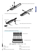
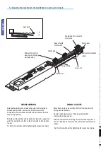
Release the gearmotor and move the door to the maximum desired open position.Loosen the fi xing screws of the microswitch 
unit. 

Slide the microswitch unit along the microswitch-support rod until it is inserted by contact on the microswitch unit actuation 
runner.

Fix the microswitch by tightening the respective screws.

5.8 Adjusting the STOP microswitch for the opening movement

Support plate microswitch
 

Microswitch actuation runner

Worm-gear

Screw-nut

Fixing screw 

Microswitch unit

Содержание A 3024

Страница 1: ...INSTALLATION MANUAL A 3024 A 3124 A 5024 A 5124 AUTOMATION FOR SWING GATES English EN 119DU92EN ...

Страница 2: ...afety and protection and release devices function properly Where necessary apply the Warning Signs so that they are clearly visible e g the gate plate Instructions and special recommendations for users Keep the barrier s areas of operations unobstructed Check that the photo cells are free of any vegetation blocking them and that there are no obstacles to the free movement of the operator Do not al...

Страница 3: ...scription 2 1 Intended use 1 Legend of symbols This symbol tells you to read the section with particular care This symbol tells you that the sections concern safety issues This symbol tells you what to say to the end users 2 Intended use and restrictions The ATI 24V gearmotor is specifically engineered to automate residential and condominium swing gates even under intensive use 3 Reference Standard...

Страница 4: ...e the path of the electrical cables complies with the command and safety instructions That there is a soundly secured to the ground mechanical stop to prevent the gate leaf gearmotor from over extending Make sure that any connections inside the case that provide continuance to the protective circuit be fitted with extra insulation as compared to the other conductive parts inside Make sure you have...

Страница 5: ...0204 1 For connections that require several sequential loads the sizes given on the table must be re evaluated based on actual power draw and distances 5 3 Cable list and minimum thickness Connections Type of cable Length of cable 1 10 m Length of cable 10 20 m Length of cable 20 30 m Control panel power supply 230V FROR CEI 20 22 CEI EN 50267 2 1 3G x 1 5 mm2 3G x 2 5 mm2 3G x 4 mm2 Flashing ligh...

Страница 6: ...has several other holes for changing the opening angle of the gate N B increasing the B measurement decreases the opening angle resulting in slower peripheral speed and greater motor thrust on the gate leaf Increasing measurement A increases the opening angle resulting in greater peripheral speed and reduced motor thrust on the gate leaf With the gate closed apply the anchoring plate to the gate l...

Страница 7: ...ve the stem N B we suggest lubricating using neutral grease the endless screw and the bushing upon installation Begin mounting the gearmotor to the two brackets M8 self locking nut Endless screw Carter Stem Motor terminal block Control panel terminal block Motor 1 N1 M1 C Fa1 Rc1 C Ra1 Motor 2 N2 M2 C Fa2 Rc2 C Ra2 ZL 19N N M Connection to motor F Fa Microswitch limit switch of motor on aperture R...

Страница 8: ...croswitch unit actuation runner Fix the microswitches unit by tightening the respective screws DURING CLOSURE Move the wing to no closer than 100 mm from the end stop during closure detail B Unscrew the fixing screws of the group deceleration microswitch during closure Slide the microswitch unit along the microswitch support rod until it is inserted by contact on the microswitch unit actuation runn...

Страница 9: ...ull the gate manually To re lock the gate simply insert and turn the key 5 9 Personalized key release Access door Key Release the gearmotor and move the door to the maximum desired open position Loosen the fixing screws of the microswitch unit Slide the microswitch unit along the microswitch support rod until it is inserted by contact on the microswitch unit actuation runner Fix the microswitch by ...

Страница 10: ...nght of A and B see Tab 4 Attach the rear bracket together with a supplementary bracket and fasten both to the column Open the gate maximum 90 and measure E see Tab 4 then fasten the front bracket to the gate Make the electrical connections as shown in the figure Re position and adjust the opening micro switch Motor terminal block Control panel terminal block Motor 1 Motor 2 7 Manutenzione 7 1 Manu...

Страница 11: ...flasher does not work The bulb is burnt Call assistance 8 Maintenance Date Notes Signature Periodic maintenance log for end user every 6 moths 8 1 Extra ordinary maintenance The following table serves to note down any extraordinary maintenance repairs or improvements performed by specialised firms N B Any extraordinary maintenance must be performed by specialised technicians Extra ordinary mainten...

Страница 12: ...performed _______________________________________________________________________________________ __________________________________________________________________________________________________ _ CAME S p A employs a UNI EN ISO 14001 certified and compliant environmental protection system at its plants to ensure that environmental safeguarding We ask you to keep protecting the environment as CA...

Отзывы: