


Page 10 of 20
CV-603 MPROXBLE CONTROLLER / CV-603PS-K1 MPROXBLE CONTROLLER CABINET KIT
INSTALLATION INSTRUCTIONS
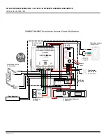
MProxBLE ASSEMBLY AND
DINRAIL ASSEMBLY
1.
Take the top of the
MProxBLE base and hook it
onto the top of the DIN rail.
Then take the bottom part with
the red clip and push it onto
the rail until it snaps into place.
2.
Slide the component along
the rail to desired location/
spacing from component A.
Power Supply ASSEMBLY
1.
Take the Snap track, align
the 2 square holes with
the mounting holes on the
cabine base.
2.
Take the 2 screws and
place them through the
holes from the back of the
cabinet. Place the washer
over the snaptrack and over
the screws. Screw the nuts
onto the screw, securing the
snaptrack is in place.
3.
Push the power supply
onto the top of the
snaptrack, into the grooves
allowing the snaptrack to
hook onto the power supply.
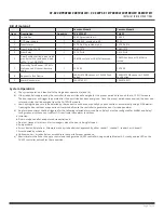
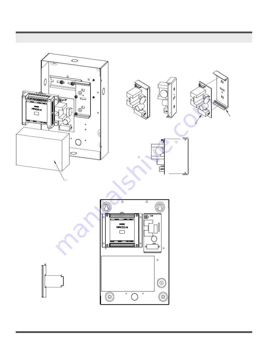
6. CV-603PS-K1 CABINET ASSEMBL
Power supply ASSEMBLY
1. Take the Snap track, align the 2 square holes
with the mounting holes on the cabine base.
2. Take the 2 screws and place them through the
holes from the back of the cabinet. Place the washer
over the snaptrack and over the screws. Screw the
nuts onto the screw, securing the snaptrack is in
place.
3. Push the power supply onto the top of the
snaptrack, into the grooves allowing the snaptrack to
hook onto the power supply.
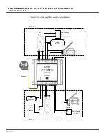
BLE Base and Dinrail ASSEMBLY
1. Take the bottom of the BLE base
and hook it onto the bottom of the DIN
rail. Then take the top part with the red
clip and push it onto the rail until it snaps
into place.
2.
to desired location/spacing from
Component A
Snaptrack
Power Supply
BLE Base
DIN Rail
Battery
Power supply ASSEMBLY
1. Take the Snap track, align the 2 square holes
with the mounting holes on the cabine base.
2. Take the 2 screws and place them through the
holes from the back of the cabinet. Place the washer
over the snaptrack and over the screws. Screw the
nuts onto the screw, securing the snaptrack is in
place.
3. Push the power supply onto the top of the
snaptrack, into the grooves allowing the snaptrack to
hook onto the power supply.
BLE Base and Dinrail ASSEMBLY
1. Take the bottom of the BLE base
and hook it onto the bottom of the DIN
rail. Then take the top part with the red
clip and push it onto the rail until it snaps
into place.
2.
to desired location/spacing from
Component A
Snaptrack
Power Supply
BLE Base
DIN Rail
Battery
Optional 12 volt, 4AH battery
provided by others.
Controller
Содержание CV-603
Страница 12: ......


