Chapter 2: System hardware
46
Chap t er 2: Sy st em hard w are
This chapter describes the hardware components of a 450 Platform link.
The following topics are described in this chapter:
l
System Components describes system components of PTP and PMP including its accessories.
l
PMP 450 MicroPoP AP describes about various cables.
l
Lightning protection unit (LPU) and grounding kit describes about lightning protection and
grounding kit.
l
Antennas and antenna cabling describes supported antennas and its accessories.
l
GPS synchronization describes UGPS and CMM4.
l
Ordering the components specifies Cambium part numbers for 450 Platform Family components
Sy st em Co m p o nent s
Point - t o- Mult ip oint ( PMP)
The PMP radio is a transceiver device. It is a connectorized or radiated outdoor unit containing all the
radio, networking, and surge suppression electronics. It can be purchased as:
l
Access Point Module (AP)
l
Subscriber Module (SM)
PMP 4 50 Plat form Family Int egrat ed or Connect orized O DU
The PMP 450i Series and PMP 450 Series ODUs are supplied in Integrated or Connectorized
configurations. The PMP 450m Series AP is supplied in Integrated configuration only.
See PMP 450m Series hardware configurations
See PMP/PTP 450i Series hardware configurations
See PMP/PTP 450b Series hardware configurations
See PMP/PTP 450 Series hardware configurations
See "PMP 450 MicroPoP Series hardware configurations" on page 32
Product variant s
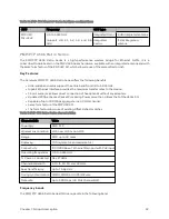
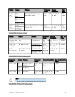
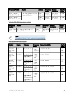
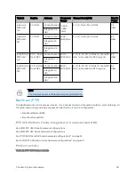
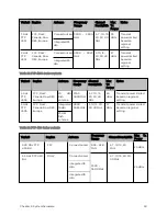
Table 16 :PMP 450m Series variants
Содержание PMP 450 Series
Страница 92: ...Chapter 2 System hardware 92 Figure 29 MicroPoP Omni antenna implementation pattern Vertical...
Страница 134: ...Chapter 3 System planning 134 Figure 51 Mast or tower installation...
Страница 135: ...Chapter 3 System planning 135 Figure 52 Wall installation...
Страница 136: ...Chapter 3 System planning 136 Figure 53 Roof installation...
Страница 137: ...Chapter 3 System planning 137 Figure 54 GPS receiver wall installation...
Страница 158: ...Chapter 3 System planning 158 Figure 61 cnMedusa Antenna...
Страница 258: ...Chapter 5 Installation 258 Figure 123 Yagi antenna alignment horizontally Figure 124 Yagi antenna alignment upward tilt...

