Chapter 1: Product description
26
Hardware components
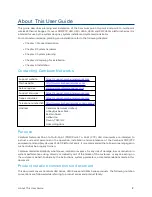
The ODU (Outdoor unit) is a self- contained transceiver unit that houses both radio and networking
electronics. The main hardware components of the PMP/PTP 450i Series are as follows:
l
PMP 450i AP
l
PMP 450i SM
l
PTP 450i BH (BHM/BHS)
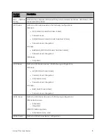
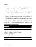
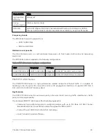
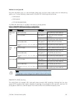
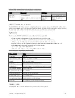
The PMP/PTP 450i Series is supplied in the following configurations:
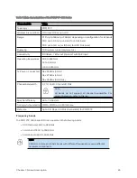
Table 4 : PMP/PTP 450i Series hardware configurations
ODU
Frequency
ODU type
PMP 450i
AP
902 to 928 MHz
Connectorized
Use with an external antenna
3.3 to 3.9 GHz
Integrated
17 dBi, 90° sector dual slant
antenna
Connectorized
Use with an external antenna
4.9 to 5.925 GHz
(support 4.9, 5.1, 5.2, 5.4 and 5.8
GHz)
Integrated
16 dBi, 90° sector antenna
Connectorized
Use with an external antenna
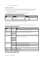
PMP
450i
SM
3.3 to 3.9 GHz
Integrated
19 dBi, SM/BH with MARS antenna
Connectorized
Use with an external antenna
4.9 to 5.925 GHz
(support 4.9, 5.1, 5.2, 5.4 and 5.8
GHz)
Integrated
23 dBi flat panel antenna
Connectorized
Use with an external antenna
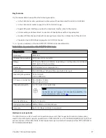
PTP 450i BH 3.3 to 3.9 GHz
Integrated
19 dBi, SM/BH with MARS antenna
Connectorized
Use with an external antenna
4.9 to 5.925 GHz
(support 4.9, 5.1, 5.2, 5.4 and 5.8
GHz)
Integrated
23 dBi flat panel antenna
Connectorized
Use with an external antenna
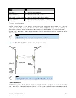
Note
The BH ODU can be configured as a BHM or a BHS in PTP mode.
PMP/ PTP 4 50 b Series
The 450b Series of products offer high- performance wireless PMP Subscriber Modules that can also
support PTP operation. Each radio is capable of operating in line-of-sight (LOS), near-LOS and non-LOS
propagation conditions. Variants support the 3 GHz and the 4.9 to 5.925 GHz frequency band.
Содержание PMP 450 Series
Страница 92: ...Chapter 2 System hardware 92 Figure 29 MicroPoP Omni antenna implementation pattern Vertical...
Страница 134: ...Chapter 3 System planning 134 Figure 51 Mast or tower installation...
Страница 135: ...Chapter 3 System planning 135 Figure 52 Wall installation...
Страница 136: ...Chapter 3 System planning 136 Figure 53 Roof installation...
Страница 137: ...Chapter 3 System planning 137 Figure 54 GPS receiver wall installation...
Страница 158: ...Chapter 3 System planning 158 Figure 61 cnMedusa Antenna...
Страница 258: ...Chapter 5 Installation 258 Figure 123 Yagi antenna alignment horizontally Figure 124 Yagi antenna alignment upward tilt...

