


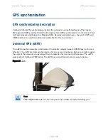


Chapter 2: System hardware GPS
synchronization
Page 2-49
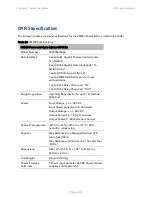
CMM3/CMMmicro
The CMM3 or CMMmicro (Cluster Management Module micro) provides power, GPS timing, and
networking connections for an AP cluster. The CMM3 is configurable through a web interface.
The CMM3 contains an 8-port managed switch that supports Power over Ethernet (PoE – this is
Cambium PoE, not the standard PoE) on each port and connects any combination of APs, BHMs,
BHSs, or Ethernet feed. The Cambium fixed wireless broadband IP networks PoE
differs from
IEEE
Standard 803.3af PoE, and the two should not be intermixed. The CMM3 can auto-negotiate speed
to match inputs that are either 100Base-TX or 10Base-T, and either full duplex or half duplex,
where the connected device is set to auto-negotiate. Alternatively, these parameters are settable.
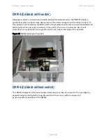
A CMM3 requires only one cable, terminating in an RJ-45 connector, for each connected module to
distribute
Ethernet signaling.
power to as many as 8 co-located modules—APs, BHMs, or BHSs. Through a browser interface
to the managed switch, ports can be powered or not.
sync to APs and BHMs. The CMM3 receives 1-pulse per second timing information from Global
Positioning System (GPS) satellites through an antenna (included) and passes the timing pulse
embedded in the 24-V power to the connected modules.
GPS status information is available at the CMM3, however
CMM3 provides time and date information to BHMs and APs if both the CMMmicro is
operating on CMMmicro Release 2.1 or later and the AP/BHM is operating on System Release
4.2 or later. See
Configuring time settings
on Page
7-18
.
CMM3
does not
provide time and date information to BHMs and APs if either the CMM3 is
operating on a release earlier than CMMmicro Release 2.1 or the AP/BHM is operating on a
release earlier than System Release 4.2.
A CMM3/CMMicro is shown in
Figure 33
and
Figure 34
.
Содержание PMP 450 Series
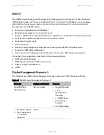
Страница 101: ...Chapter 2 System hardware GPS synchronization Page 2 40 Figure 25 Cluster Management Scenario 1...
Страница 125: ...Chapter 3 System planning Typical deployment Page 3 3 Figure 37 Wall installation...
Страница 126: ...Chapter 3 System planning Typical deployment Page 3 4 Figure 38 Roof installation...
Страница 127: ...Chapter 3 System planning Typical deployment Page 3 5 Figure 39 GPS receiver wall installation...
Страница 128: ...Chapter 3 System planning Typical deployment Page 3 6 Figure 40 GPS receiver tower or mast installation...