background image


137 


Proprietary Information: Not for use or disclosure except by written agreement with Calix. 

© Calix. All Rights Reserved. 

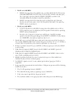
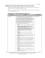
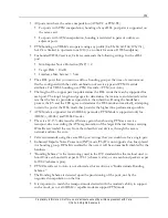
Parameter 

Description 

Valid Options  

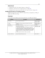
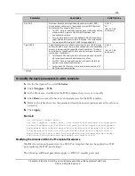
Upshift Rate Adaption 
Margin 

Downstream or upstream upshift rate adaption margin defines an 
SNR margin above the Target SNR Margin which, when exceeded, 
initiates a bitrate "upshift." For the increase to occur, the noise 
margin must stay above this value for the time specified in 
upstream or downstream Upshift Rate Adaptation Time. Applies 
only when dynamic rate adaptation is specified.   


For IPTV, Calix recommends a value of 3 dB above target for 

both upstream and downstream directions. 


For HSI, Calix recommends a value of 1 dB above target for 

both upstream and downstream directions. 

0.0-31.0 
3.0 ‡ 

(dB, in 0.1 dB increments) 

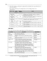
Downshift Rate Adaption 
Time 

Downstream or upstream downshift rate adaptation time (sec).  

Applies only when dynamic rate adaptation is specified. Specifies 
the duration in seconds that the downstream or upstream noise 
margin must stay below the downstream or upstream Downshift 
Rate Adaptation Margin before the modem decreases the 
downstream or upstream data rate. The valid range is 0 to 16383 
seconds. 0 disables the feature. 

0-16383 
60 ‡ 

Upshift Rate Adaption Time 

Downstream or upstream upshift rate adaptation time (sec).  

Applies only when dynamic rate adaptation is specified. Specifies 
the duration in seconds that the downstream or upstream noise 
margin must stay above the Rate Adaptation Upshift Margin 
Downstream before the modem increases the downstream data 
rate. The valid range is 0 to 16383 seconds. 0 disables the feature. 

0-16383 
60 ‡ 

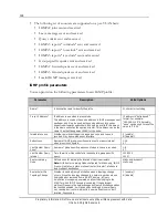
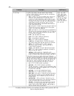
Enhanced Impulse Noise 
Protection 

Downstream or upstream enhanced impulse noise protection 
mode that used in conjunction with Retransmission which is a 
proprietary method for retransmitting data and requires a DSL 
modem that is Broadcom based and PhyR enabled, or G.INP 
capable CPE. 


For IPTV, Calix recommends using the "g.inp" or "phyr" setting 

in the downstream and upstream direction. 

Note:

 The "PhyR" setting is a special mode that gives precedence 

to rate. Yet, PhyR is only enabled as long as rate is not 
compromised. Therefore, the "phyr-fixed" setting allows you to 
force PhyR to be enabled, regardless of impact to rate. 


Impulse Noise Immunity (G.INP) enhances techniques to 

protect against impulse noise for ADSL2, ADSL2+, and 
VDSL2. 


Impulse noise is a noise event of limited duration that can 

degrade one or more transmitted symbols. Unlike the various 
types of continuous noise found on DSL, impulse noise has a 
short duration and may repeat, either randomly or periodically. 


Impulse  noise that does not appear to repeat periodically, but 

occur as unpredictable events is termed SHINE (Single high 
impulse noise event). 


Impulse noise caused by noise from electrical mains and thus 

repeats at a constant period related to the local AC power 
frequency is termed REIN (Repetitive electrical impulse noise). 

G.INP specifies a physical layer retransmission method for 
enhancing INP. 

none ‡, g.inp, phyr, phyr-
fixed 

Содержание E7-2

Страница 1: ...E7 2 E5 48 E3 48C R2 4 xDSL Applications Guide December 2015 220 00811 Rev 12...

Страница 2: ......

Страница 3: ...Configuring an Ethernet Interface 26 Configuring a Link Aggregation Interface 33 Creating the Service VLAN s 47 Additional multicast addressing considerations 50 Adding the Uplink Interface s to VLAN...

Страница 4: ...losure except by written agreement with Calix Calix All Rights Reserved Chapter 3 Reference Information 215 System Support Capacities 216 xDSL Support Capacities 221 E Series LED Behavior 223 E Series...

Страница 5: ...orts VDSL2 cards and the E3 48C E5 48 and E5 48C products that supports the equivalent of the VDSL2 line cards For specific procedures on provisioning Ethernet elements such as VLANs Ethernet ports an...

Страница 6: ...g Guide This document provides engineering and planning information for the Calix E7 Ethernet Service Access Platform ESAP and Calix E3 48C Ethernet Service Access Node ESAN It describes the features...

Страница 7: ...ications Guide These application guides show you how to provision subscriber services using specific technologies assuming that the system is already installed and turned up Maintenance and Troublesho...

Страница 8: ...T1 Pseudowire Applications Guide Calix C7 VoIP Services Guide Calix Application Note Using the ONT VoIP Configuration File Completing Residential Gateway and SIP Configuration File Intake Forms Calix...

Страница 9: ...ll Rights Reserved Chapter 1 VDSL Applications Overview This chapter describes VDSL2 applications and the Calix E Series VDSL2 solution Topics Covered This chapter covers the following topics An overv...

Страница 10: ...p and terminate it on an existing DLC or analog POTS port on a switch line bay One E7 2 VDSL2 48 line card can be plugged into a Calix E7 2 shelf to create a compact high density DSL overlay node with...

Страница 11: ...l loop as well as traditional Class 5 TDM Voice Switch consolidation applications The All Digital Loop provides high speed data services to all subscribers with the VoIP POTS functionality provided as...

Страница 12: ...ull set of subscriber services and network topology protocols Interface Capacity The Calix E7 2 VDSL2 48C line card combines VDSL2 ADSL2 fallback subscriber ports and corresponding 900 integrated spli...

Страница 13: ...carried over the service loop using standard Voice Frequency carriers 300 to 3400 Hertz A line card integrated voice splitter separates the voice from the data service for each subscriber signal extra...

Страница 14: ...orts 3 and 4 LAG group may NOT include ports across the pair boundary For example a LAG with ports 1 and 3 or 2 and 3 are not supported Multiple modes of DSL deployment All xDSL ports on the VDSL2 lin...

Страница 15: ...gacy mode this mode is only supported on the C7 and E5 series Calix products and NOT supported on the E Series is distinctly different than the other modes in that ATM VC are connected directly to ind...

Страница 16: ...MOP Migrating Standalone E7 Systems to an E7 Modular Chassis for instructions on how to migrate multiple standalone E7 systems into a unified E7 modular chassis Calix E7 Maintenance and Troubleshootin...

Страница 17: ...second card in the E7 2 same chassis Both the RT and CO nodes are fully and only equipped with E7 2 VDSL2 48C line cards while they could also use transport cards for example 10GE 4 in the MCC to aggr...

Страница 18: ...18 Proprietary Information Not for use or disclosure except by written agreement with Calix Calix All Rights Reserved...

Страница 19: ...and network configuration specific procedures see the Calix E7 User Guide or the Calix E3 48 E5 48 E5 48C User Guide See the E7 Maintenance and Troubleshooting Guide for a procedure on VDSL2 Single E...

Страница 20: ...Overview Configuring the Network Uplink s This chapter describes how to configure the network uplink s for E Series VDSL2 services If the network contains a number of E Series nodes such as in a 10GE...

Страница 21: ...face even when it is being used in a standalone manner An Ethernet port can be either assigned to the Ethernet interface associated with the port or assigned to an existing LAG interface Before you ca...

Страница 22: ...SFP ports 1G fiber modules in SFP or SFP ports 2 5G fiber modules in SFP ports 10G fiber modules in SFP ports X X X X X X X X X X The following rules apply for stand alone E7 shelves and Modular Chass...

Страница 23: ...State Service state of port While troubleshooting a port that has Admin State enabled no alarms either use the CLI command show alarm include suppressed or from the web browser interface temporarily...

Страница 24: ...set the ports on the active card to a common LACP priority value and then set the LAG ports on the standby card to another common priority value The priority value on the active card ports must be lo...

Страница 25: ...pported for XFP ports Fixed speed setting forces the speed to the value specified Note See the configuration guidelines above for the forced speed setting supported for various ports auto module rate...

Страница 26: ...ick Apply to commit the changes For CLI set eth port port ID speed duplex flow ctrl interface eth gos cos queue cfg bcast max rate unk mcast max rate dlf max rate lacp priority lacp timeout admin stat...

Страница 27: ...RSTP and LAG networking protocols are supported Examples of an edge port would include GE ports to managed CPE a GE 10GE port to external equipment which may use different tagging levels or GPON ports...

Страница 28: ...two cards in the same E7 shelf That is one port on each E7 card For Modular Chassis systems RSTP is only supported on MCC shelf interfaces For E7 20 systems RSTP is only supported on SCP cards Note No...

Страница 29: ...e card as Ethernet downlink Edge interfaces that are members of the outer VLAN ingress double tagged traffic from the downlink ports will not flow upstream resulting in a service interruption As a wor...

Страница 30: ...map that you want to associate to the E Series Ethernet port interface is already created Parameters You can provision the following parameters for Ethernet interfaces Parameter Description Valid Opti...

Страница 31: ...to the speed of the bridge The slower the media the higher the cost Note Leave the default value unless you are certain of a modified value to assign as the cost of service 1 200000000 4 Policy Map N...

Страница 32: ...ant link 1ad results in the E7 transmitting BPDUs with a DA of 01 80 C2 00 00 08 Use this selection when the E7 is connected to an 802 1ad compliant switch with redundant link 1d 1ad LACP Tunnel LACP...

Страница 33: ...nt Number of failed audit quality intervals within the polling window that will indicate an interface failure for IQA to take an alarm or OOS action 1 60 10 Interval Min Frames Minimum number of frame...

Страница 34: ...this E7 Ethernet port interface is where all classification is first performed on ingress traffic if customer facing The E7 Ethernet interface is also expected to add replace or remove one or more VLA...

Страница 35: ...ports that comprise a LAG can be on the same line card or on two different line cards in the same shelf Link aggregation provides two principle values to the network operator Point to point link prot...

Страница 36: ...led LAG cross card N No or disabled LACP Min Ports 1 LACP Max Ports 2 Note Ports added to the LAG that exceed the LACP Max Ports parameter are designated as standby ports Example Cross Card LAGs The c...

Страница 37: ...LACP Cross Card active standby LACP Min Ports 1 LACP Max Ports 1 Card 1 Ethernet port LACP Priority 100 Card 2 Ethernet port LACP Priority 128 LAG per card and RSTP As a network configuration RSTP ca...

Страница 38: ...ds in the same E7 shelf That is one port on each E7 card For Modular Chassis systems RSTP is only supported on MCC shelf interfaces For E7 20 systems RSTP is only supported on SCP cards For cross card...

Страница 39: ...1 by default Access interfaces do not support a Native VLAN however tag actions can be used to assign untagged traffic to a VLAN ID All network connections ERPS RSTP LAG DHCP servers multicast routers...

Страница 40: ...cally checks the number of File Check Sequence FCS errors received as a percentage of total frames received on an interface An interface that exceeds the provisioned thresholds can be set to generate...

Страница 41: ...e The VLAN IGMP Mode proxy The IGMP profile Router Learning Mode static The IGMP profile Router Solicit On Topology Change N disabled The LAG interface is designated as a static router port through th...

Страница 42: ...ociate to the E7 Ethernet port interface is already created Parameters You can provision the following parameters for LAG interfaces Parameter Description Valid Options Name Name of LAG interface or a...

Страница 43: ...the speed of the bridge The slower the media the higher the cost Note Leave the default value unless you are certain of a modified value to assign as the cost of service 1 200000000 4 Policy Map Name...

Страница 44: ...ant link 1ad results in the E7 transmitting BPDUs with a DA of 01 80 C2 00 00 08 Use this selection when the E7 is connected to an 802 1ad compliant switch with redundant link 1d 1ad LACP Tunnel LACP...

Страница 45: ...r a specific interval to be considered valid 1 2147483647 100 LACP Cross Card LAG only Whether LAG cross card protection is enabled allowing ports on two cards to be configured into a LAG active stand...

Страница 46: ...ally the upstream side of the LAG is configured for the LAG master lower value When the LACP system priority is changed a 2 second downtime will occur where no traffic passes through the LAG When prov...

Страница 47: ...r transparent LAN TLAN to segregate traffic for different services or subscribers on the same network and separate device management control messages from traffic See Provisioning VLAN Ranges on page...

Страница 48: ...ed previously the C tag also known as the customer tag is used to uniquely identify a customer typically is used on a per port basis The S tag also known as the service provider tag is used to logical...

Страница 49: ...h ports should be a member of a multicast group It can provide a local response if the channel already exists on the E Series or it will forward those requests upstream to a multicast router or anothe...

Страница 50: ...on subscriber links and result in tiling Therefore Calix recommends NOT using 224 0 0 x or any of the 32 multicast IP addresses that are not unique at the L2 MAC address level for video channel assign...

Страница 51: ...r s IP host requests and is granted a new IP address using DHCP When DHCP snooping is enabled on a subscriber VLAN the E Series drops all DHCP server communication originating from subscriber Ethernet...

Страница 52: ...riber MAC addresses to the E Series forwarding table Disabling MAC Learning should only be done with point to point services and is NOT appropriate for a multi point Ethernet LAN ELAN service or other...

Страница 53: ...popped in the downstream Once a tag is used as a single tagged VLAN it cannot also be used in double tagged VLANs For example if VLAN 300 is single tagged It cannot be used as the inner tag of a doub...

Страница 54: ...in order to reduce the amount of IGMP traffic that must be processed higher in the network Disabling Report Suppression allows more Report messages to be allowed up through the network proxy Causes th...

Страница 55: ...ile any VLAN has MAC Learning disabled Calix recommends leaving MAC Learning in the default enabled mode Disabling MAC learning causes traffic within the VLAN to be flooded to all egress interfaces wi...

Страница 56: ...Management 5 In the IGMP Mode list select the IGMP mode Calix recommends that VLANs used for video services be set to suppress snoop or proxy enable snooping Note DSL only supports a single MVR VLAN i...

Страница 57: ...te vlan vlan ID show vlan vlan id detail igmp counters members onts show vlan vlan id detail igmp counters mac mcast members onts Configuring DHCP Relay Option 82 and LDRA This topic shows you how to...

Страница 58: ...ed Untrusted interfaces are snooped for client DHCP traffic Trusted interfaces are snooped for DHCP server traffic Note All E7 GPON ONT Ethernet ports are implicitly Untrusted and the Trusted attribut...

Страница 59: ...k group the port within the xDSL bonded link group with the lowest port value will be selected to fill the port field in the Circuit ID string Remote ID options Subscriber ID of the port on which the...

Страница 60: ...lready have DHCP Relay Agent information will be dropped Configuration guidelines The following additional constraints only affect VLANs with DHCP Snooping that are provisioned on Ethernet and xDSL po...

Страница 61: ...3 In the Option 82 LDRA Enabled checkbox select the checkbox to enable this feature 4 In the Option 82 Policy list select whether to drop or overwrite packets with Option 82 on ingress packets 5 In t...

Страница 62: ...default gpon system default remote id subscriber id fsan serial number mac addr none set access identifier profile eth system default gpon system default circuit id calix format tr101 format calix for...

Страница 63: ...where there is no text You can select multiple VLANs to edit using the Control click and Shift click keys Make any modifications using the top edit row Click Apply from the toolbar when the modificat...

Страница 64: ...e specified range of VLAN memberships Note Use Shift click or Ctrl click to select multiple interfaces from the column 5 Click the direction button to add the interfaces to the range of VLAN membershi...

Страница 65: ...erface has the multicast router You can add many interfaces to the static location For example if the system is connected to the multicast router via RSTP you would want to add the static location to...

Страница 66: ...he Ethernet LAG interface or ERPS domain must exist to add it to a VLAN membership To make an interface a VLAN member 1 On the Navigation Tree click VLANs 2 Click the Provisioning tab 3 In the table o...

Страница 67: ...tion guidelines above Note If the E7 system is set to Modular Chassis mode the Ethernet port interfaces are indicated with a shelf card port location For example EthIntf 1 2 G1 6 Click Ok For CLI add...

Страница 68: ...ltiple service ports Note For information about system profiles unrelated to VDSL2 services refer to the Calix E7 User Guide or the Calix E3 48 E5 48 E5 48C User Guide Profiles referenced in service p...

Страница 69: ...subscriber except the customer tag is unique per subscriber In this case it would be ideal to define the match list and tag action pair such that multiple subscriber ports can reference it This is acc...

Страница 70: ...profiles Specifies the SIP service configuration information that previously resided in a SIP configuration file in a primary and a secondary location TDM Voice Gateway profiles Specifies the port num...

Страница 71: ...o a service VLAN The match list is applied to a service tag action that is then associated with an xDSL port service Service tag actions Marks the traffic with the appropriate VLAN and priority value...

Страница 72: ...priority value as is set for downstream traffic The priority value must also be consistent with the class of service type as defined in the Ethernet port CoS table Class of service parameters You can...

Страница 73: ...Rate Aggregate shaping rate for the port specified in Mbps The allowed range is 1 10000 Alternately select none to indicate that shaping should not be done none or keyword unshaped Enter Value 1 10000...

Страница 74: ...hin the networking domain Add Tag The add tag action adds an outer tag either on all packets on an interface or only on packets that match a specified VLAN ID or P bit Add 2 Tags The add 2 tag action...

Страница 75: ...action is performed on all packets entering the specified interface except for the packet traffic on VLANs that have an associated membership with the interface When the match rule is set to ignore a...

Страница 76: ...data VLANs are double tagged VLAN per port for data traffic Single voice service VLAN Single video service VLAN Configure the following 1 Create a voice VLAN and a video VLAN and add the interface to...

Страница 77: ...ction Performed selection is add 2 tags or add and change ignore any untagged Enter Value then enter a VLAN ID 2 4093 Required field To add VLAN tag actions to an E Series Ethernet interface 1 On the...

Страница 78: ...bscriber traffic to determine the service in which it belongs A match list can contain both tagged and untagged match rules up to 12 tagged rules and up to 16 untagged rules Untagged match rules can m...

Страница 79: ...d GPON if the PON CoS setting allows it Match list and rule parameters You can provision the following parameters for match list and rules Parameter Description Valid Options Name Name of service matc...

Страница 80: ...Required field To create a service match list 1 Access the profile page From CMS On the Navigation Tree click CMS In the Work Area click Profile E5 48 E3 48C E7 ONT Service Tagging Match Lists Locall...

Страница 81: ...g that can be specified by name or by numeric VLAN ID which ranges from 1 4095 untagged indicates that only untagged traffic should be matched ignore indicates that the VLAN ID should not be examined...

Страница 82: ...classifying traffic into services Marking the service tag actions are for marking the traffic with the appropriate VLAN and P bit required by the service This topic describes how to create service ta...

Страница 83: ...arking of packets from the subscriber port into the service VLAN You have the following options for determining the added or changed tag values Specify the VLAN value explicitly This option is used fo...

Страница 84: ...ask on page 100 if you do not want to use the system default b Assign the map to the xDSL port associated interface on page 182 or leave the system default map access assignment c Create a service tag...

Страница 85: ...as N 1 An additional tag can be added to limit the size of a group for improved reliability A service carried on an N 1 VLAN applies to multiple subscriber ports allowing a single match list and tag a...

Страница 86: ...rity is not supported for this scenario The same service tag action can be used on multiple xDSL ports Each E Series shelf or E7 Modular Chassis system has a capacity of 256 service tag actions For co...

Страница 87: ...re supported The following tag actions are supported for VLANs with IGMP enabled Add tag ony supported for untagged traffic Change tag Services provisioned with DSCP or IP Precedence translation to P...

Страница 88: ...agged is defined when adding the service to a port Upstream traffic is marked with P bit 0 The upstream traffic on a service VLAN must have the same P bit value as is set for downstream traffic Before...

Страница 89: ...outer tag when the P bit Source is set to Specify P bit Note When the value of copy is selected the E Series honors the P bit value of the incoming traffic and passes the existing P bit value upstrea...

Страница 90: ...Tag 11 In the P Bit Source list select where to derive the P bit value for marking the outer tag for services provisioned on xDSL ports Specify P Bit requires that you enter the P bit value for marki...

Страница 91: ...N The E Series Ethernet port Trunk and Edge interfaces are always associated with at least one VLAN through the native VLAN attribute VLAN 1 by default The native VLAN ID is specified on the interface...

Страница 92: ...1 100 Match pbit P bit value range 0 7 that specifies the VLAN priority value to match Alternately if pbit any is used or the parameter is not specified the P bit value is not considered pbit 0 to pb...

Страница 93: ...se on ingress traffic packets See Creating a Policy Map and Policies on page 93 For CLI add class rule rule index to map c map name match all add class rule rule index to map c map name match pbit P b...

Страница 94: ...value greater than default when using jumbo frames for example 9000 kbyte at higher rates Typically set the burst to the amount of traffic sent in twice the round trip time Also consider whether the t...

Страница 95: ...that specifies the VLAN priority value The default setting of pbit none does not alter the existing pbit The upstream traffic on a service VLAN must have the same P bit value as is set for downstream...

Страница 96: ...used for packet classification on DiffServ networks defined in RFC 2474 and RFC 2475 to IEEE 802 1p priority bit values to classify traffic priority Traffic coming from the subscriber to xDSL Access...

Страница 97: ...e or traffic internal to the access node will be discarded at random service unaware See Creating a Policy Map for L3 Priority Mapping on page 102 DSCP traffic classes The DSCP traffic classes are des...

Страница 98: ...om the P Bit Source list 2 On the xDSL port associated interface where you are going to be provisioning the data or video service select the name of the DSCP profile to use from the DSCP IP Precedence...

Страница 99: ...Medium High 0 1 1 1 1 2 2 2 2 3 3 3 3 4 4 4 4 5 5 0 0 0 Best Effort BE Assured Forwarding AF gives assurance of delivery under prescribed conditions Expedited Forwarding EF dedicated to low loss low l...

Страница 100: ...he changes to the map For CLI set dscp map name default cs0 af11 af12 af13 af21 af22 af23 cs3 af31 af41 ef cs6 cs7 show dscp map show dscp map name Creating and Modifying an IP Precedence Map This top...

Страница 101: ...ialog do the following a In the Name box enter a name that describes the use of this custom profile b In each of the designated IP Precedence value lists select the correlating P bit value following s...

Страница 102: ...eate policy maps see the following topics Creating a Class Map and Rules on page 90 Creating a Policy Map and Policies on page 93 Note The upstream traffic on a service VLAN must have the same priorit...

Страница 103: ...to CoS 5 1 Create class map CoS 5 Create class rule Match pbit pbit any Match Outer 100 Match Inner ignore Match DSCP 40 equates to CS5 2 Create policy map CoS 5 Create Policy class map CoS 5 Out pbi...

Страница 104: ...imit 15 max burst size 4 create policy 3 class map mix3 set P bit 3 create policy 4 class map mix4 set P bit 4 create policy 5 class map mix5 set P bit 5 create policy 6 class map mix6 set P bit 6 cre...

Страница 105: ...to apply to individual Ethernet services on xDSL ports even when the modem is trained at a higher rate Typically a single bandwidth profile is applied to many subscriber ports Yet for each level of d...

Страница 106: ...affic classes The recommended DSCP for expedited forwarding is 101110 46 Assured Forwarding AF PHB gives assurance of delivery under prescribed conditions The IETF defines the Assured Forwarding behav...

Страница 107: ...actions applied to xDSL services The priority of traffic as defined in the Layer 3 DSCP table or IP precedence table or The P bit value specified in the service tag action The E7 calculates a burst si...

Страница 108: ...se m suffix for Mb s or g for Gb s in whole number increments 0 2048kpbs 0 1000Mbps 1Gbps kbps in 64k increments Peak Rate for Upstream Peak information rate for upstream traffic Where rates may be sp...

Страница 109: ...am box enter a value that specifies the minimum rate to allow traffic to flow upstream c In the Peak Rate for Upstream box enter a value that specifies the un guaranteed maximum bandwidth for upstream...

Страница 110: ...Multicast Maps Identifies the map of optional global multicast IP addresses that a subscriber service can join when this multicast profile is used The multicast map is an optional parameter of the mu...

Страница 111: ...p on vlan on vlan ip Creating an MVR Profile and MVR VLAN Addresses The Multicast VLAN Registration MVR feature gives you the ability to register multicast VLANs with a subscriber unicast VLAN MVR wor...

Страница 112: ...AN carrying both HSI and unicast video left node and separate VLANs for data and unicast video right node In this model multicast video is isolated from unicast video via separate VLANs One or more de...

Страница 113: ...hat is associated to the Multicast Profile used when provisioning the service on the subscriber port The ONTs do not support tagged and untagged match rules on the same ONT for video services Only one...

Страница 114: ...ofile and MVR VLAN addresses 1 Access the profile page From CMS On the Navigation Tree click CMS In the Work Area click Profile E3 48C E5 48 E7 ONT Profile Service Multicast MVR Locally on the node On...

Страница 115: ...ap can contain up to eight distinct multicast IP address ranges not overlapping When both multicast white list and multicast address map are applied to a service only the white list ranges are passed...

Страница 116: ...ulticast map when creating a multicast profile For CLI create mcast map m name add range to mcast map m name mcast m range delete mcast map index remove range index from mcast map m name set mcast map...

Страница 117: ...plied to a service only the white list ranges are passed on to the ONT or xDSL port The multicast map is ignored Maximum of 16 Multicast white lists are supported per service where each Multicast whit...

Страница 118: ...lds To create a multicast white list and address ranges 1 Access the profile page From CMS On the Navigation Tree click CMS In the Work Area click Profile E3 48C E5 48 E7 ONT Profile Service Multicast...

Страница 119: ...name from interface vdsl interface eth svc service remove mcast white list list name from ont port ont port eth svc service remove mcast white list list name from dsl bond interface vdsl interface eth...

Страница 120: ...auto For ERPS and G 8032v2 ring configurations The ring node with a direct connection to the mrouter can be provisioned as IGMPv3 and operate as v3 If at least one node in the ring does not support IG...

Страница 121: ...etwork If a connected C7 is using IGMP proxy then snooping must be enabled on the video VLAN Otherwise snooping should be disabled set to N With Router Learning Mode configured for static only IGMP Pr...

Страница 122: ...e 2 is discarded If the VLAN in Node 1 transitions from v2 to v3 then a v3 General Query is sent to Node 2 and any v2 traffic from Node 2 is discarded For an xDSL interface the IGMP operation mode v2...

Страница 123: ...ce transitions back to v3 The IGMP version of the IGMP Query must match the provisioned VLAN setting in the associated IGMP profile if the version setting is set to either v2 or v3 If there is a chanc...

Страница 124: ...ample 192 168 1 100 Alternately none can be used to reset the value to 0 0 0 0 Immediate Leave Whether a multicast stream is dropped as soon as a Leave is received May be overridden per interface Y en...

Страница 125: ...60 Router Port Purge Time Purge time in seconds for router ports 60 600 260 Proxy VLAN IGMP Version The VLAN IGMP operating version v2 v3 auto Source Specific Multicast Start Address IP address that i...

Страница 126: ...ly of the same profile To achieve cross talk elimination with vectoring vectoring capable CPE must be deployed in conjunction with the E Series units In addition E Series vectored lines must be in the...

Страница 127: ...idered as shared spectrum Transmission strength and frequencies on both ends of the line the DSLAM and the modem are managed to reduce the overall noise floor For optimal performance Calix recommends...

Страница 128: ...nex A b8 12 VDSL2 Annex B 17 MHz US0 as in ADSL2 annex B b7 1 VDSL2 Annex B 7 MHz US0 as in ADSL2 annex A b7 2 b7 4 VDSL2 Annex B 8 8 MHz US0 as in ADSL2 2 annex M b7 3 VDSL2 Annex B 12 MHz US0 as in...

Страница 129: ...g a In the Navigation Tree click the xDSL port of interest b In the Work Area click Port Status Status c View the following fields Actual Vectoring Mode G 993 5 Line Vectoring State steady Operation S...

Страница 130: ...object If the same parameters are specified in both templates the values defined in the last applied template are applied to the xDSL port If parameters specified in the first applied template are not...

Страница 131: ...min State Service state of the xDSL port enabled no alarms enabled disabled Interface Name of DSL bonded interface of which to add this port as a member EthIntf any existing bonded interface Descripti...

Страница 132: ...annexm ADSL2 ADSL2 Annex M standards specification vdsl2 ITU T G 993 2 standards specification for profiles 8a 8b 8c 8d 12a 12b and 17a vdsl2mm VDSL multi mode Enables the port to automatically detect...

Страница 133: ...meter allows the operator to select fast or interleaved path in G dmt and in other modes to configure the interleaver to behave similarly to fast path minimal delay little to no impulse noise protecti...

Страница 134: ...multimedia data receiving quality For bonded VDSL2 services Calix recommends a setting of 2 for the upstream direction For IPTV Calix recommends a value of 3 for the downstream direction and a value o...

Страница 135: ...ctions For IPTV Calix recommends a value of at least 8 dB for both upstream and downstream directions For bonded VDSL2 services Calix recommends a value of 10 dB for the upstream direction 0 0 31 0 6...

Страница 136: ...Header Compression Whether ATM header compression is implemented leaving more bits available for data Note An increase in the downstream data rate is only realized with this feature if Broadcom based...

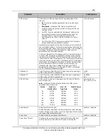
Страница 137: ...am or upstream noise margin must stay above the Rate Adaptation Upshift Margin Downstream before the modem increases the downstream data rate The valid range is 0 to 16383 seconds 0 disables the featu...

Страница 138: ...lse noise protection against SHINE symbols 0 63 4 Single High Impulse Noise Ratio symbols Downstream or upstream Single High Impulse Noise Event SHINE Ratio NDR in 001 increments As stated in G 998 4...

Страница 139: ...the same copper loop binder group a nus0 VDSL2 Annex A POTS compatibility do not use band US0 a eu 32 a eu 36 a eu 40 a eu 44 a eu 48 a eu 52 a eu 56 a eu 60 a eu 64 a eu 128 VDSL2 Annex A POTS compat...

Страница 140: ...m Hz 127 5 to 0 0 0 values are negative RFI Bands Band 1 16 Start Specifies the start frequency in KHz for RFI bands 1 to 16 where each frequency is an integer and has a resolution of 1 kHz The start...

Страница 141: ...On the Navigation Tree click E7 E3 48C E5 48 or E5 48C 2 Click Template DSL 3 In the Workarea double click the DSL template that you want to modify 4 Click PSD to access the basic level of parameters...

Страница 142: ...tream Target SNR 5 8 Advanced PTM Override auto auto ATM Header Compression enabled enabled Downstream Rate Adaption Mode dynamic dynamic Upstream Rate Adaption Mode dynamic dynamic Downstream Downshi...

Страница 143: ...us upshift adapt time 30 ds enhanced inp phyr us enhanced inp phyr atm header compress enabled Creating an Ethernet Security Profile This topic shows you how to create an Ethernet security profile th...

Страница 144: ...LAN services this parameter must be set to all tunnel all discard all tunnel or any previously created filter DOS Attack Detection Whether to enable or disable Denial Of Service DOS attack detection a...

Страница 145: ...l frames The E Series already has two system default filters that either discard all discard or pass all tunnel all L2CP protocol frames for all ranges The L2CP filter is referenced from the Ethernet...

Страница 146: ...ult To create an L2CP filter 1 Access the profile page From CMS On the Navigation Tree click CMS In the Work Area click Profile E3 48C E5 48 E7 ONT Profile Security L2CP Locally on the E Series On the...

Страница 147: ...oE traffic transparently as long as the Clients BRAS are operating normally illegal packets will be dropped Up to one service on each xDSL interface including bonded links may resolve to a VLAN with a...

Страница 148: ...BNG MACs are allowed six hexadecimal digits in the range 0 FF optionally separated by colons none Allowed BNG MAC 4 Allowed trusted Broadband Network Gateway BNG defined in TR 101 MAC address or OUI A...

Страница 149: ...ll the port field in the Circuit ID string Remote ID options Subscriber ID of the port on which the DHCP lease request is received The first 63 characters of the Subscriber ID text field are inserted...

Страница 150: ...net based multi pair bonding PTM ITU G 998 2 G bond When a port in a bonding group fails or is administratively disabled services continue on the ports that still function within the bandwidth availab...

Страница 151: ...process the E5 and the CPE agree to determine the DSL mode automatically attempting to train the port at the DSL mode that provides the highest line performance possible ATM Mode is supported for all...

Страница 152: ...Valid Options Name Name of the xDSL bonding group text string Admin State Service state of the bonding group enabled disabled Subscriber ID Subscriber ID information such as phone number or account nu...

Страница 153: ...up 1 Choose ports on a VDSL2 card intended for DSL pair bonded services considering the following The member ports must have the same Service Type either all VDSL2 or all ADSL service types All ports...

Страница 154: ...uch as an account number or address d In the Description box enter further information that would be helpful to identify the bonding group e In the IGMP Immediate Leave list select whether a multicast...

Страница 155: ...ate leave ds min rate us min rate admin state show dsl bond interface detail vlans show dsl bond interface intfc name detail eth svc members vlans show dsl port port advanced all basic inventory psd s...

Страница 156: ...port is configured To provision the IP Host for a Static protocol configuration you must select static for the Host Protocol parameter and then enter the Static IP Static IP Mask and Static IP Gatewa...

Страница 157: ...address for the VDSL2 card to use in routing its traffic to the SIP server if the host protocol is static This attribute is ignored yet preserved if the host protocol is DHCP 4 byte IP address Ping Wh...

Страница 158: ...teway object On current systems using the SIP Gateway with per port provisioning method a separate SIP dial plan profile can be created and attached to the SIP port service When an applied dial plan i...

Страница 159: ...em default 2 411 system default 3 2 9 0 9 6 system default 4 1 2 9 0 9 9 system default 5 011 0 9 T system default 6 S 0 9 2 Parameters You can provision the following parameters for creating a dial p...

Страница 160: ...e is played during call forwarding sequence d Dial tone is played during a call forwarding sequence Comma Outside dial tone is played if preceded by a 9 n no local disconnect Pound indicator b Must im...

Страница 161: ...fer to the above table 6 Click Create For CLI add rule p index to dial plan p name pattern token delete dial plan name set dial plan p name rule name digit short timer digit long timer show dial plan...

Страница 162: ...etects a failure or is disabled the SIP client will again try to switch back to the primary SIP proxy The secondary proxy server can only be configured if the proxy server is configured as an IP addre...

Страница 163: ...enable Silence Suppression third order priority codec selected enabled unselected disabled T1 Timer ms T1 and T2 are SIP timers T1 is an estimate of the round trip time the client will start to retra...

Страница 164: ...Agent will consume the hook flash and provide the service locally When disabled unselected then the hook flash is passed to the Softswitch for processing selected enabled unselected disabled RTP DSCP...

Страница 165: ...com 5060 1 63 character text string none Country Code E 164 Country code designator Protocol Country Variant profile This attribute specifies the country code where the service is being deployed This...

Страница 166: ...ind the SIP line None for supported switch types that are not in the list none zte huaw syla eric cs2k bell Required fields Default To create a SIP gateway profile 1 On the Navigation Tree click the u...

Страница 167: ...P configuration file version to the same VDSL2 there will be two configuration files present in the VDSL2 card s flash One that is currently in use by the VDSL2 card applied file One that is a newly r...

Страница 168: ...the configuration file instance specified in the IP Host A configuration name is specified by instance number alone or by voip 1 through 4 voip 1 Instance for VOIP 1 voip 2 Instance for VOIP 2 voip 3...

Страница 169: ...rvice associated with specific gateways Now a single trunking gateway can be specified for each E Series or P Series device These devices are then associated with the specific trunking gateway by sett...

Страница 170: ...DSCP CS6 48 cs7 DSCP CS7 56 RTP Ethernet QoS Ethernet QoS for RTP packets 0 7 6 DHCP Filter Whether to use the server IP address as the DHCP offer filter When enabled if the associated IP host is usi...

Страница 171: ...eway service groups Parameter Description Valid Options ID Index of the TDM Gateway service group Any value between 1 1000 inclusively Description Unique name that indicates the entire description of...

Страница 172: ...y Domain Name FQDN Parameters You can provision the following parameters for H 248 gateway profiles Parameter Description Valid Options Name Name of the H 248 gateway profile A 31 character text strin...

Страница 173: ...nations RTP text string ESA Mode Whether to enable the ESA mode selected enabled unselected disabled RTP Codec RTP code to use u law a law Packet Rate Packet rate packets msec 10ms 20ms Country Code x...

Страница 174: ...ifies the H 248 gateway properties for the VDSL2 H 248 gateway services Parameters You can provision the following parameters for H 248 gateway Parameter Description Valid Options Name Name of the H 2...

Страница 175: ...ver that is reachable by the system and place it in the VDSL2 flash memory The cancel action can be invoked before the apply action is performed either while the retrieve action is still in progress o...

Страница 176: ...FTP server Source File Path File path of the configuration file on your FTP server Force Select the Force box to force the system to retrieve the file as specified Required field To manage coefficien...

Страница 177: ...ervices Configuring Data Services This section describes how to create data services on xDSL ports Topics Covered This section covers the following topics in bold that are part of the overall E Series...

Страница 178: ...ng the data services configuration process ensure the following steps of the turn up process have been completed 1 The network uplinks for VDSL2 services are configured Ethernet port interfaces Ethern...

Страница 179: ...rious parameters that are more likely to be modified on an xDSL port for data service You can also apply a previously created DSL template to multiple ports for ease of configuration See Creating and...

Страница 180: ...B of margin above target SNR before power cutback is allowed This corresponds to a maximum SNR margin of 10 dB for supporting HSI Advanced DSL Port Parameters DS or US downshift rate adaptation margin...

Страница 181: ...ng Basic Action Apply Template 3 In the Template list select from the list of previously created DSL templates 4 Click Apply Template For CLI apply dsl template t name to dsl port port To modify the x...

Страница 182: ...If the interface is connected to a single subscriber device then the system does not need to query the interface and it can terminate the delivery of the Multicast stream right away This mode of oper...

Страница 183: ...ervices Profiles referenced in service provisioning When provisioning subscriber services on a VDSL2 card xDSL port you set up information that is common to multiple subscribers and maintained in prof...

Страница 184: ...stem Inner Tag Specifies the customer VLAN ID if the Service Tag Action references Specified in Service for the Inner Tag none any VLAN created on the system Required fields Default To create a data s...

Страница 185: ...e agent functionality allows for a PPPoE session access method where the access node inserts a Access Loop Identification ALID tag to the PPPoE frames to be sent upstream toward the Broadband Network...

Страница 186: ...all the active sessions and statistics are available and the PPPoE stack is enabled which passes through PPPoE traffic transparently as long as the Clients BRAS are operating normally illegal packets...

Страница 187: ...net to associate with an xDSL port service or an xDSL bonding group service Configuration guidelines To identify a specific IP host for the purposes of securing the subscriber s traffic the IP address...

Страница 188: ...ost IP addresses to the subnet and binds the subnet to an xDSL port Before starting Before starting this procedure you will need to provision a service on the xDSL port where you want to configure the...

Страница 189: ...dress or subnet 2 Click Static IP Subnet 3 If there are multiple Ethernet services provisioned on the selected port or bonding group at the top of the Work Area click the drop down list to select the...

Страница 190: ...rt into the service VLAN The Calix E Series supports the following data service models over IP on VDSL2 ports VLAN per Service where each service is assigned a dedicated VLAN where multiple subscriber...

Страница 191: ...mplate on page 129 Layer 3 priority map on page 96 Security Profile on page 143 Bonding groups if required on page 150 Note See Calix xDSL Best Practices for a description of the physical layer factor...

Страница 192: ...y sensitive applications like voice and online gaming Specifies a minimum of 4 ms delay interleaved interleaves DSL frames to optimize error protection in the presence of impulse noise sources that ar...

Страница 193: ...tream and downstream directions For VDSL2 applications Calix recommends a value of 5 dB below target for both upstream and downstream directions DS or US upshift rate adaption margin Defines an SNR ma...

Страница 194: ...On the Navigation Tree click the xDSL port of which you want to modify parameters 2 In the Workarea click Port Provisioning Basic 3 Refer to the table above for the parameter descriptions and options...

Страница 195: ...des IGMP proxy functionality for all devices behind it enabled disabled use vlan setting Subscriber ID Subscriber ID information such as phone number address or account number 47 character text string...

Страница 196: ...the similar task of subscriber service activation then consists of referencing the existing profiles and sometimes providing subscriber specific information to complement the profiles Both service pr...

Страница 197: ...an existing service as follows In the Navigation Tree click XDSL In the Work Area click Port Multicast White List Create and then select the service and multicast white list s Any existing multicast w...

Страница 198: ...elines To identify a specific IP host for the purposes of securing the subscriber s traffic the IP address must be provided and optionally the MAC address information To identify an IP subnet a MAC ad...

Страница 199: ...ociate with an IP address Any established service name Type IP address or hostname of the primary SIP configuration server IP address hostname Static IP Host Address IP Address Static IP address for t...

Страница 200: ...IP host or subnet 4 Click Create to open the Create Ethernet Service IP Subnet dialog box 5 Reference the table above to configure the parameters 6 If you chose to add a subnet address fill in the re...

Страница 201: ...DSL2 applications 3 Configure voice subscriber services Overview of the VDSL2 voice services provisioning Provisioning a Voice port Configuring a SIP service Configuring a TDM Gateway service Configur...

Страница 202: ...d to configure a voice service IP address or domain name of your VoIP provider s SIP server or outbound proxy SIP server H 248 media gateway controller or C7 TDM gateway IP address to assign to the lo...

Страница 203: ...ce After completing the steps outlined above continue with the following topics in this section to configure a service on a Voice port Configure a Voice port on page 203 Configure SIP service on a Voi...

Страница 204: ...standards to reduce the perception of noise and echo on the line GR 909 loss plan Rx Tx 4 2 is more compatible with GR 303 type phone systems ANSI loss plan Rx Tx 9 3 is more compatible with American...

Страница 205: ...cific information to complement the profiles Although an IP Host is configured for voice services on a VDSL2 card it is not required to explicitly reference it when creating a SIP service because it a...

Страница 206: ...to the SIP VoIP service any available plans Enable Direct Connect Whether to enable support for Direct Connect Hot Line and Direct Connect Timer Warm Line select to enable clear to disable Direct Con...

Страница 207: ...the gateway address 4 byte IP address Static IP Mask If the host protocol is static IP network mask assigned to the VDSL2 card This attribute is ignored yet preserved if the host protocol is later swi...

Страница 208: ...TDM voice gateway refer to the Calix C7 VoIP Services Guide Profiles referenced in service provisioning When provisioning subscriber services on a VDSL2 Voice port you set up information that is commo...

Страница 209: ...tion Optional description field for the port subscriber address name or service String up to 27 characters blank Service Type Form view only Type of voice service to create SIP TDM Gateway H 248 Gatew...

Страница 210: ...s traffic to the SIP server This attribute is ignored yet preserved if the host protocol is later switched to DHCP 4 byte IP address S VLAN Outer Tag Outer tag VLAN ID customer specific for the servic...

Страница 211: ...ofile are affected Profiles cannot be deleted while they are in use Profiles can also be reloaded for a specific VDSL2 Voice port from the Service Table by clicking Refresh Media gateway consideration...

Страница 212: ...P 4 byte IP address Static IP Mask If the host protocol is static the IP network mask assigned to the VDSL2 card This attribute is ignored yet preserved if the host protocol is later switched to DHCP...

Страница 213: ...er source changes from AC to battery backup during an AC power failure the system switches off lower priority xDSL services leaving the remaining battery power available for higher priority voice conn...

Страница 214: ...214 Proprietary Information Not for use or disclosure except by written agreement with Calix Calix All Rights Reserved...

Страница 215: ...All Rights Reserved Appendix A Reference Information This appendix provides general reference information about the Calix E Series Ethernet service access platform Topics Covered This appendix covers...

Страница 216: ...municates with the best server and then only sends to the next server if it does not get a response Where best is determined by the success rate of getting responses to recent requests MAC address Tab...

Страница 217: ...limit 768 Maximum number of service VLANs with DHCP Snoop enabled per VDSL2 line card 48 per system 256 VLANs that may be IGMP enabled 32 VLANs that may have PPPoE profile assigned E7 2 only 24 Calix...

Страница 218: ...ies depending on the number of VLAN tags applied to the payload plus allowances for Preamble Delimiter and interframe gap 8 bytes Preamble Delimiter 14 bytes header not including VLAN tags 4 bytes inn...

Страница 219: ...le card E7 shelf This number does not include devices or E7s subtended from the ring including the MCE shelves of an E7 2 modular chassis MC node Interconnected rings for a chain of ERPS rings 3 Unit...

Страница 220: ...d rules and up to 16 untagged rules for each Ethernet port 32 OUIs are allowed in an untagged match list Service tag actions 256 DSL port templates 264 SIP Remote Configuration Profiles GPON 512 SIP G...

Страница 221: ...rings Note that for E7 2 modular chassis with VDSL2 based MCCs in an ERPS ring the maximum VDSL2 combo subscribers node and nodes ring are lower than in other configurations These capacities are shown...

Страница 222: ...VC supports up to 6 VCs between port and CPE with 1 to 1 mapping of VC per service i e IPTV Data TR 69 mgmt etc Bonding Group Capacity 24 Adjacent ports recommended for DSL Bonding Bonding of ADSL2 Fa...

Страница 223: ...fic Green LED POTS port that stays on indicates indicates at least one POTS subscriber port is operating correctly the system is up operational and is off hook Red LED 10GE indicates a module is inser...

Страница 224: ...her States Off Off All Short Red Equipment Mismatch Green blinking Yellow blinking Red blinking E7 20 card inserted in E7 2 Yellow rapid blinking Yellow rapid blinking Red rapid blinking E7 20 SCP car...

Страница 225: ...ct has a service affecting alarm reported against it or any of its parents For example An ONT parent is the system object A Card parent is the shelf and then the system user disabled Indicates an obje...

Отзывы: