5)
Selector for minimum flow temperature at heating start-up
(Tmin Y).
Adjustable from 20°C to 40°C.
Factory setting: 20°C.
6)
Maximum limit temperature selector.
Adjustable from 35°C to 65°C.
Factory setting: 50°C
In case a higher value has been set at point 7 of the front panel,
this will be restricted to the limit value.
7)
NZ
Neutral zone regulation selector.
Adjustable from 1,5°C to 6°C.
Factory setting: 2°C (equivalent to ±1°C).
If the flow temperature variation remains within the temperature
value selected in the neutral zone, the mixing valve remains
inactive.
When cooling, the neutral zone automatically takes the value 1,5°C.
8)
RF(%)
Return sensor regulation selector.
Adjustable from 0% to 100%.
Factory setting: 80%.
This selector is used to optimise the system output according to
the difference in temperature between flow and return (
∆
T).
∆
T is calculated as a percentage of the flow temperature
calculated on the characteristic curve.
∆
TY = (T
flow
set Y-Tmin Y)
∆
T =
∆
TY · %set · 0,3.
T
return
set Y = T
flow
set Y -
∆
T.
Example with factory setting values:
flow temperature calculated on the characteristic curve,
T
flow
set Y = 40°C (project conditions).
Thus:
∆
TY = (40 - 20) = 20°C
∆
T = 20 · 0,8 · 0,3 = 4,8°C
T
return
set Y = 40 - 4,8 = 35,2°C.
If the return temperature measured (T
return
Y) is
≠
T
return
set Y, the controller will modify the characteristic curve, moving
it upwards or downwards, to move the return temperature to the
set value.
This continuous comparison prevents room overheating caused
by gratuitous heat sources modifying the heating load.
There is no effect on the cooling function.
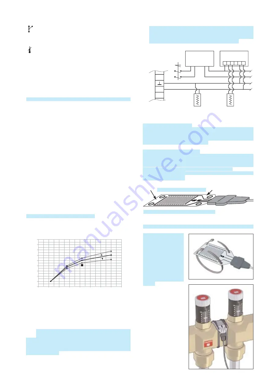
Curve with return temperature regulation
9)
Auxiliary contact. This contact opens when the mixing valve is
completely closed to the secondary and open to the primary.
It can be used to shut down the pump of the primary circuit or
the boiler.
10)
UR
Relative humidity sensor wiring. This sensor is used to
detect the limiting value of relative humidity to prevent
condensation on the cooling surface.
This is calibrated for RH= 80÷85%. When the calibrated value
is reached, this will cause the following state: mixing valve
closed, pump ON.
If various zones at risk of condensation are to be controlled, the
humidity sensor must be connected to a suitable interface kit
(transformer, converter and humidity sensor). Up to 12 converters
plus sensor can be connected to a single transformer.
Humidity sensor control
At the start of each cooling season, the operating condition of the
sensor should be checked by placing a damp pad on its surface;
this operation should cause the mixing valve to close and the yellow
LED, point 1 on the front panel, to light.
Positioning humidity sensor
The umidity sensor must be positioned at the point where there is
most risk of the formation of condensation, depending on the
characteristics of the system. It must be positioned with the printed
part upward, according to the diagrams shown below.
Fix ends E, taking care that the central part adheres perfectly to the
manifold or to the piping.
Layouts for the correct positioning of the max RH% limit sensor.
The sensor should be
fixed to the manifold
installed in the position
where the RH% relative
humidity value has not
to exceed the safety
limits. Fixing in ensured
by inserting the two
straps contained in the
package through the
suitable holes on the
sensor.
15
20
25
30
35
40
45
50
55
60
25
20
15
10
5
0
-5
-10
-15
T
FLOW
(
°
C)
T
OUTSIDE
(
°
C)
Treturn 35,2
°
C
LH side
ter
m
inal strip
0
1
N
L
UR
SENSOR RH%
code 150050
SENSOR RH%
code 150050
1 2 3 4 5 6
CONVERTER
code 150051
TRANSFORMER
code 150052
24 V
220 V
SR
Upper side: printed circuit
Lower side: sited on the cooling surface
E
E


