background image

SERVICE MANUAL 

CALIBRATION 

3-17 

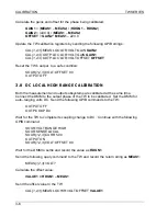
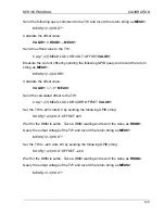
Close the TW’s output relay: 

OUTPUT ON 

Wait for the DMM to settle and record the voltage as 

MEAS1

Set the TW to 80 Hz. 

SOUR:FREQ 80.0 

Wait for the DMM to settle and record the voltage as 

MEAS2

Set the TW to 160 Hz. 

SOUR:FREQ 160.0 

Wait for the DMM to settle and record the voltage as 

MEAS3

Set the TW to 320 Hz. 

SOUR:FREQ 320.0 

Wait for the DMM to settle and record the voltage as 

MEAS4

Set the TW to 500 Hz. 

SOUR:FREQ 500.0 

Wait for the DMM to settle and record the voltage as 

MEAS5

Set the TW to 60 Hz and open the output relay. 

SOUR:FREQ 80.0 
OUTPUT OFF 

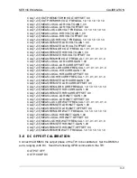
Calculate the calibration constants: 


VALUE1

 = 120.0 / 

MEAS1 

VALUE2

 = 120.0 / 

MEAS2


VALUE3

 = 120.0 / 

MEAS3


VALUE4

 = 120.0 / 

MEAS4


VALUE5

 = 120.0 / 

MEAS5


Update the remote low range frequency calibration of the TW by sending the following 
GPIB string: 

CAL

{1,2,3}

:OUTP:REM:LOR:VOLT:FREQCAL

 VALUE1 VALUE2 VALUE3 VALUE4 VALUE5


Содержание TrueWave TW1750

Страница 1: ...tek com Web www programmablepower com TrueWave Switching Amplifier Service Manual Models TW5250 TW3500 TW1750 This Service Manual is incomplete without the TrueWave Operation Manual which contains detailed descriptions of the TrueWave system installation instructions and operating instructions March 2011 Document No M161469 03 Rev C Via Acquanera 29 22100 Como tel 031 526 566 r a fax 031 507 984 i...

Страница 2: ......

Страница 3: ...ses only Notice of Copyright TrueWave Switching Amplifier Service Manual 2010 AMETEK Programmable Power Inc All rights reserved Exclusion for Documentation UNLESS SPECIFICALLY AGREED TO IN WRITING AMETEK PROGRAMMABLE POWER INC AMETEK a MAKES NO WARRANTY AS TO THE ACCURACY SUFFICIENCY OR SUITABILITY OF ANY TECHNICAL OR OTHER INFORMATION PROVIDED IN ITS MANUALS OR OTHER DOCUMENTATION b ASSUMES NO RE...

Страница 4: ...ii This page intentionally left blank ...

Страница 5: ...onnel and equipment safety Always ensure that facility AC input power is de energized prior to connecting or disconnecting any cable In normal operation the operator does not have access to hazardous voltages within the chassis However depending on the user s application configuration HIGH VOLTAGES HAZARDOUS TO HUMAN SAFETY may be normally generated on the output terminals The customer user must e...

Страница 6: ...e instructions of AMETEK is opened modified or disassembled in any way without AMETEK s consent or is used in combination with items articles or materials not authorized by AMETEK The Buyer may not assert any claim that the Products are not in conformity with any warranty until the Buyer has made all payments to AMETEK provided for in the Purchase Order Agreement PRODUCT RETURN PROCEDURE 1 Request...

Страница 7: ...D 1 6 1 6 HOUSEKEEPING BOARD HSKP 1 7 1 7 POWER CONDITIONER MODULE 1 8 1 7 1 RECTIFIER INPUT 1 8 1 7 2 POWER FACTOR CORRECTION PFC INPUT 1 8 1 7 3 DC DC CONVERTER 1 9 1 8 AMPLIFIER MODULE 1 9 1 9 GLOSSARY 1 10 SECTION 2 MAINTENANCE AND TROUBLESHOOTING 2 1 GENERAL 2 1 2 2 FACTORY REPAIR 2 1 2 3 REQUIRED TEST EQUIPMENT 2 2 2 4 PERIODIC MAINTENANCE 2 2 2 5 FAULT SYMPTOMS TROUBLESHOOTING 2 3 2 6 DISAS...

Страница 8: ... 3 15 EXTERNAL PHASE REFERENCE CALIBRATION 3 22 3 16 PHASE A TO PHASE B CALIBRATION 3 23 3 17 PHASE A TO PHASE C CALIBRATION 3 25 3 18 EXTERNAL GAIN CONTROL CALIBRATION 3 27 3 19 LOW RANGE CURRENT CALIBRATION 3 28 3 20 LOCAL LOW RANGE WATTS CALIBRATION 3 29 3 21 REMOTE LOW RANGE WATTS CALIBRATION 3 30 3 22 LOW RANGE CURRENT FREQUENCY CALIBRATION 3 31 3 23 LOCAL LOW RANGE WATTS FREQUENCY CALIBRATIO...

Страница 9: ...S FIGURE 1 1 TW 5250 1 2 FIGURE 1 2 DIGITAL CONTROL BOARD BLOCK DIAGRAM 1 4 FIGURE 1 3 ANALOG PROCESSOR BOARD BLOCK DIAGRAM 1 6 FIGURE 1 7 POWER CONDITIONER MODULE BLOCK DIAGRAM 1 8 LIST OF TABLES TABLE 2 1 REQUIRED TEST EQUIPMENT 2 2 TABLE 2 2 FUSES 2 3 TABLE 2 3 TROUBLESHOOTING 2 4 TABLE 3 1 CALIBRATION TEST EQUIPMENT 3 1 TABLE 4 1 PARTS LIST 4 1 TABLE 5 1 TRUEWAVE SYSTEM DIAGRAMS 5 1 ...

Страница 10: ...TABLE OF CONTENTS TW SERIES viii This page intentionally left blank ...
Страница 11: ...es at the module or board level is most valuable should the service person find it necessary to investigate a suspected fault or malfunction within the power source 1 2 SYSTEM OVERVIEW Figure 1 1 shows a simplified block diagram of the TW system The 3 phase input voltage is delivered via the input filter to the power module s where it is rectified providing bus voltages for the amplifier s Voltage...

Страница 12: ...PWR MOD ØC RECTIFIER OR PFC DC DC BACKPLANE AMPLIFIER ØA AMPLIFIER ØB AMPLIFIER ØC 290VDC BUS 290VDC BUS 290VDC BUS 290VDC BUS 290VDC BUS 290VDC BUS BACKPLANE OUTPUT FILTER INPUT FILTER 3Ø INPUT 208 VAC OR 400 VAC W NEUTRAL ØA OUT ØB OUT ØC OUT ANALOG PROCESSOR BOARD DIGITAL CONTROL BOARD FRONT PANEL DISPLAY AND CONTROL ...

Страница 13: ...ck and input filter to the power module s through W1 2 and 3 where it is rectified via the PFC or rectifier input stage s The rectified voltages are then delivered to the DC DC converter s where 290V buses are produced and delivered via the backplane board to the amplifier s A 48V bus is also produced by the DC DC converter s and delivered via the backplane to the HSKP board see section 1 6 The am...

Страница 14: ...cessor operating with a 16 bit data bus The processor system memory consists of one 256K x 16 20ns static RAM one 256K x 16 90ns FLASH ROM 64K x 8 120ns PROM and 8K x 8 EEPROM The PROM is used during boot for processor execution the EEPROM is used for calibration data the FLASH is used for processor execution and the RAM is used for system data storage For more information on the MC68332 processor...

Страница 15: ...efault or user defined values Performs system self test Enters main control loop The main control loop reads the keypad for user input updates the displays and data buffers with current readback values from the Analog Processor Board and interprets SCPI strings received from either the RS 232 or GPIB bus Additionally the Analog Processor Board is monitored for fault conditions If a fault occurs th...

Страница 16: ...s main control loop All waveform generation and measurements are handled by the DSP Current mode of operation is also controlled by the DSP Hardware faults are monitored by the DSP and appropriate actions are taken by the DSP when a fault occurs The sinewave references are constructed using three waveform DACs and one amplitude DAC driving the voltage reference The DSP updates each of the waveform...

Страница 17: ...calibration scaling and presentation to the user 1 6 HOUSEKEEPING BOARD HSKP The HSKP board receives 48Vdc input from the power module s via the backplane board where the 48V inputs are paralleled and delivered via J7A connector to the HSKP board The 48V is then delivered to the housekeeping circuit and also via the J3 connector to power the fans of the fan panel assembly The housekeeping power su...

Страница 18: ... stage is delivered through a soft start circuit and rectified by a 3 phase bridge rectifier developing a 380 Vdc bus When the system is configured for USA input the rectifier is wired as a 3 phase full wave bridge rectifier When the system is configured for INTERNATIONAL input the rectifier is wired as a 3 phase half wave rectifier The rectified 380 Vdc bus is then delivered to the DC DC stage of...

Страница 19: ...hops switches the 380 Vdc bus supplied by the rectifier or PFC input stage at a rate of 140 kHz The output transformer and three full wave bridge rectifier circuits then generate the two 290 Vdc and 48 Vdc buses The output transformer and associated rectifier circuitry also produces a 27 Vdc bus which provides power for the DC DC PWM control circuit 1 8 AMPLIFIER MODULE The amplifier module is a f...

Страница 20: ...the amplifier bus voltages and output neutral to chassis voltages for overvoltage conditions Also monitored are amplifier heatsink temperatures as well as output voltage and current feedback signals all of which are reported back to the Analog board 1 9 GLOSSARY DAC Digital to Analog Converter DC DC DC DC Converter HSKP Housekeeping Supply Board PFC Power Factor Correction Power Factor Ratio of th...

Страница 21: ...ed without authorization WARNING Hazardous voltages are present when operating this equipment Please read the Safety Notice at the beginning of this manual before performing any installation operation or maintenance procedures 2 2 FACTORY REPAIR TW systems requiring repair during their warranty period should be returned to Elgar for service Unauthorized repairs performed by anyone other than Elgar...

Страница 22: ...Failure to comply can result in serious electrical shock to individuals coming in contact with live voltages at exposed terminals when the unit is energized Once the unit is de energized a wait period of at least 5 minutes should be observed to allow internal capacitors to discharge 2 4 PERIODIC MAINTENANCE Other than calibration and cleaning no periodic maintenance is required on TW systems Calib...

Страница 23: ...des of a TW system Since the TW is such a complex system any fault could be caused by one or more of several assemblies For that reason this manual will list the suspect assemblies in order with the first assembly listed being the most likely cause of the fault Along with the suspect assemblies listed the cables connecting those assemblies are also suspect and must be inspected and replaced if nec...

Страница 24: ...ly installed Re energize unit and test Unit comes up momentarily and shuts off immediately De energize unit and perform disassembly steps 2 6 1 thru 2 6 5 Insure that the connectors of cable 5161524 01 are properly seated Re assemble unit and test Loss of GPIB communication unable to communicate with SW system via GPIB IEEE 488 2 connector Probable cause is ribbon cable connector damage De energiz...

Страница 25: ...ng the following procedure in reverse and referring to the Final Assembly drawing 5161469 located in Section 5 of this manual WARNING Prior to beginning disassembly procedures ensure that AC power has been disconnected from the TW system During re assembly of the unit it is very important that all removed cable ties and adhesives are replaced and that cables are routed as they were originally Inco...

Страница 26: ...s may be covered by white quality seals and therefore the seals will need to be broken Remove cover as shown above 2 6 2 Loosen the front panel by removing the remaining 8 screws securing the front panel to the chassis The front panel will still be connected to the unit by several ribbon cables Extreme care must be taken not to damage these cables ...

Страница 27: ...OOTING 2 7 2 6 3 Remove the fan panel power cables from the Analog board connectors J10 and J11 as shown above 2 6 4 Remove the 4 pan head screws two screws on either side of unit securing the fan panel assembly to the chassis as shown above ...

Страница 28: ...emoved from the chassis as shown above Extreme care must be taken not to damage any components on the Analog board as the fan panel assembly is being removed 2 6 6 Slightly separate the Power On switch end of the front panel from the chassis as shown above Using the index finger of the left hand gently push the Power On switch from the back side of the front panel out through the front side ...

Страница 29: ... back through the front panel 2 6 8 Remove cables from J1 J4 J7 J8 on Analog board and J2 J6 on Control board The front panel assembly can now be completely removed The Housekeeping board can also be removed if necessary by disconnecting the cables to J3 J7A and J28B and then removing the 7 screws securing the board to the chassis ...

Страница 30: ...emove the Analog and Control boards from the front panel assembly remove the 8 mounting screws securing the boards to the panel and gently separate the boards 2 6 10 Remove the 4 screws attaching the ribbon cable bracket to the chassis assembly as shown above ...

Страница 31: ... on model that secure the top bracket to the modules as shown above 2 6 12 To remove the ribbon cable bracket remove the top screw only that secures the bracket to the air baffle as shown above The bottom screw mechanism wraps around the edge of the air baffle and thus does not need to be removed ...

Страница 32: ...ES 2 12 2 6 13 Remove the 4 screws that secure the Signal board to the air baffle 2 6 14 The Signal board can now be removed by disconnecting the 1 2 or 3 ribbon cable connector s depending on model from the Amplifier module s as shown above ...

Страница 33: ...e air baffle as shown above 2 6 16 Disconnect both the small enable connector P1 and the large input power connector P2 from each of the power modules as shown above Note There may be a small amount of RTV securing the P1 connector and the locking tabs of P2 must be depressed before the connector can be removed ...

Страница 34: ...NCE AND TROUBLESHOOTING TW SERIES 2 14 2 6 17 Remove the air baffle by lifting straight out as shown above 2 6 18 Any module can now be removed by first gently pulling module towards the front of unit to unlock ...

Страница 35: ...ar panel assembly can now be detached by removing the 13 screws around the rear perimeter of the chassis 4 screws on the left side 5 screws on the right side and 4 screws on the bottom When removing the rear panel assembly from the chassis extreme care must be taken not to damage any of the ribbon cable assemblies connected to the rear panel assembly ...

Страница 36: ...MAINTENANCE AND TROUBLESHOOTING TW SERIES 2 16 This page intentionally left blank ...

Страница 37: ...quipment listed below or equipment with equivalent capabilities can be used to calibrate the TrueWave s output and measurement The measurement equipment listed meets the 4 1 ratio required by many calibration standards Description Accuracy Model Model No Digital Multimeter 6 digits AC AC Volts Range 0 350 VAC Accuracy 0 025 Fluke 1271 with high accuracy option 12 Power Analyzer three phase RMS Cur...

Страница 38: ...OPHA 0 0 0 0 0 0 0 0 0 0 CAL UNIQ OPHAB 0 0 0 0 0 0 0 0 0 0 CAL UNIQ MOPHAB 0 0 0 0 0 0 0 0 0 0 CAL UNIQ OPHAC 0 0 0 0 0 0 0 0 0 0 CAL UNIQ MOPHAC 0 0 0 0 0 0 0 0 0 0 CAL UNIQ GEXTG 1 0 CAL UNIQ OEXTG 0 0 The second step for calibration is clearing the phase specific calibration constants Each phase has its own calibration data The 1 2 3 symbol should be replaced by 1 2 or 3 For a TW1750 only CAL1...

Страница 39: ...L 1 2 3 MEAS LOCAL HIR CURR OFFSET 0 0 CAL 1 2 3 MEAS LOC HIR CURR FREQCAL 1 0 1 0 1 0 1 0 1 0 CAL 1 2 3 MEAS REMOTE LOR CURR GAIN 1 00 CAL 1 2 3 MEAS REMOTE LOR CURR OFFSET 0 0 CAL 1 2 3 MEAS REM LOR CURR FREQCAL 1 0 1 0 1 0 1 0 1 0 CAL 1 2 3 MEAS REMOTE HIR CURR GAIN 1 00 CAL 1 2 3 MEAS REMOTE HIR CURR OFFSET 0 0 CAL 1 2 3 MEAS LOCAL LOR WATT GAIN 1 00 CAL 1 2 3 MEAS LOCAL LOR WATT OFFSET 0 0 CA...

Страница 40: ...uired offset DAC setting VALUE1 256 RDNG1 RDNG1 RDNG2 Set the dc offset calibration register OUTPUT OFF CAL UNIQ DCDAC A B C VALUE1 3 7 DC LOCAL LOW RANGE CALIBRATION Both the measurement and output subsystems are calibrated at the same time Connect the DMM to the output phase of the TW to be calibrated Set the DMM for auto ranging volts DC Send the following GPIB commands to the TW OUTPUT OFF OUT...

Страница 41: ...1 0 MEAS1 Send the calculated offset to the TW CAL 1 2 3 MEAS LOC LOR CURR OFFSET VALUE1 Set the TW to 220 volts DC by sending the following GPIB string SOUR 1 2 3 VOLT OFFSET 220 Wait for the DMM to settle Take a DMM reading and record the value as RDGN1 Query the output voltage of the TW and record the return string as MEAS1 MEAS 1 2 3 VOLT Set the TW to 220 volts DC by sending the following GPI...

Страница 42: ...rement and output subsystems are calibrated at the same time Connect the DMM to the output phase of the TW to be calibrated Set the DMM for auto ranging volts DC Send the following GPIB commands to the TW OUTPUT OFF OUTP COUP DC Wait for the TW to complete its coupling change to DC Continue with the following GPIB command SOUR VOLT RANGE HIGH SOUR SENSE LOCAL SOUR 1 2 3 CURR 5 00 OUTPUT ON SOUR 1 ...

Страница 43: ...ing as MEAS1 MEAS 1 2 3 VOLT Set the TW to 440 volts DC by sending the following GPIB string SOUR 1 2 3 VOLT OFFSET 440 Wait for the DMM to settle Take a DMM reading and record the value as RDGN2 Query the output voltage of the TW and record the return string as MEAS2 MEAS 1 2 3 VOLT Calculate the gains and offset for the phase being calibrated GAIN1 MEAS1 MEAS2 RDGN1 RDGN2 GAIN2 880 0 MEAS1 MEAS2...

Страница 44: ...CURR 5 00 OUTPUT ON SOUR 1 2 3 VOLT OFFSET 0 0 Wait for the DMM to settle and record the value as RDGN1 Send the following query command to the TW and record the return string as MEAS1 MEAS 1 2 3 VOLT Calculate the offset value VALUE1 RDGN1 MEAS1 Send the offset value to the TW CAL 1 2 3 MEAS REM LOR VOLT OFFSET VALUE1 Measure the current offset by sending the following GPIB query and record the r...

Страница 45: ...MEAS2 OFFSET GAIN2 MEAS1 220 0 Update the TW calibration registers by sending the following GPIB strings CAL 1 2 3 MEAS REM LOR VOLT GAIN GAIN2 CAL 1 2 3 OUTP REM LOR VOLT GAIN GAIN1 CAL 1 2 3 OUTP REM LOR VOLT OFFSET OFFSET Reset the TW s output to a safe condition SOUR 1 2 3 VOLT OFFSET 0 0 OUTPUT OFF 3 10 DC REMOTE HIGH RANGE CALIBRATION Both the measurement and output subsystems are calibrated...

Страница 46: ...te the offset value VALUE1 1 0 MEAS1 Send the calculated offset to the TW CAL 1 2 3 MEAS REM HIR CURR OFFSET VALUE1 Set the TW to 440 volts DC by sending the following GPIB string SOUR 1 2 3 VOLT OFFSET 440 Wait for the DMM to settle Take a DMM reading and record the value as RDGN1 Query the output voltage of the TW and record the return string as MEAS1 MEAS 1 2 3 VOLT Set the TW to 440 volts DC b...

Страница 47: ...OLT OFFSET 0 0 OUTPUT OFF 3 11 LOCAL LOW RANGE FREQUENCY CALIBRATION Connect the TW output to the DMM Set the DMM up for auto ranging AC voltage Set the TW into AC coupling local sense 40 Hz 120V and low range by sending the following GPIB strings OUTP COUP AC SOUR VOLT RANGE LOW SOUR SENSE LOCAL SOUR FREQ 40 0 SOUR 1 2 3 VOLT 120 00 Close the TW s output relay OUTPUT ON Wait for the DMM to settle...

Страница 48: ...ate the local low range frequency calibration of the TW by sending the following GPIB string CAL 1 2 3 OUTP LOC LOR VOLT FREQCAL VALUE1 VALUE2 VALUE3 VALUE4 VALUE5 Close the TW s output relay OUTPUT ON Wait for the DMM reading to settle and record the value as RDNG1 Query the TW s output put voltage with the GPIB string below and record this value as MEAS1 MEAS 1 2 3 VOLT Set the TW s frequency to...

Страница 49: ...record this value as MEAS4 MEAS 1 2 3 VOLT Set the TW s frequency to 500 Hz with the following GPIB command SOUR FREQ 500 0 Wait for the DMM reading to settle and record the value as RDNG5 Query the TW s output put voltage with the GPIB string below and record this value as MEAS5 MEAS 1 2 3 VOLT Set the TW s frequency to 60 Hz and open the output with the following GPIB commands SOUR FREQ 60 0 OUT...

Страница 50: ...e the TW s output relay OUTPUT ON Wait for the DMM to settle and record the voltage as MEAS1 Set the TW to 80 Hz SOUR FREQ 80 0 Wait for the DMM to settle and record the voltage as MEAS2 Set the TW to 160 Hz SOUR FREQ 160 0 Wait for the DMM to settle and record the voltage as MEAS3 Set the TW to 320 Hz SOUR FREQ 320 0 Wait for the DMM to settle and record the voltage as MEAS4 Set the TW to 500 Hz ...

Страница 51: ...tage with the GPIB string below and record this value as MEAS1 MEAS 1 2 3 VOLT Set the TW s frequency to 80 Hz with the following GPIB command SOUR FREQ 80 0 Wait for the DMM reading to settle and record the value as RDNG2 Query the TW s output put voltage with the GPIB string below and record this value as MEAS2 MEAS 1 2 3 VOLT Set the TW s frequency to 160 Hz with the following GPIB command SOUR...

Страница 52: ...z and open the output with the following GPIB commands SOUR FREQ 60 0 OUTP OFF Calculate the measurement system frequency compensation values VALUE1 RDGN1 MEAS1 VALUE2 RDGN2 MEAS2 VALUE3 RDGN3 MEAS3 VALUE4 RDGN4 MEAS4 VALUE5 RDGN5 MEAS5 Update the TW s calibration data with the following GPIB command CAL 1 2 3 MEAS LOC HIR VOLT FREQCAL VALUE1 VALUE2 VALUE3 VALUE4 VALUE5 3 13 REMOTE LOW RANGE FREQU...

Страница 53: ...SOUR FREQ 320 0 Wait for the DMM to settle and record the voltage as MEAS4 Set the TW to 500 Hz SOUR FREQ 500 0 Wait for the DMM to settle and record the voltage as MEAS5 Set the TW to 60 Hz and open the output relay SOUR FREQ 80 0 OUTPUT OFF Calculate the calibration constants VALUE1 120 0 MEAS1 VALUE2 120 0 MEAS2 VALUE3 120 0 MEAS3 VALUE4 120 0 MEAS4 VALUE5 120 0 MEAS5 Update the remote low rang...

Страница 54: ...S2 MEAS 1 2 3 VOLT Set the TW s frequency to 160 Hz with the following GPIB command SOUR FREQ 160 0 Wait for the DMM reading to settle and record the value as RDNG3 Query the TW s output put voltage with the GPIB string below and record this value as MEAS3 MEAS 1 2 3 VOLT Set the TW s frequency to 320 Hz with the following GPIB command SOUR FREQ 320 0 Wait for the DMM reading to settle and record ...

Страница 55: ...alibration data with the following GPIB command CAL 1 2 3 MEAS REM LOR VOLT FREQCAL VALUE1 VALUE2 VALUE3 VALUE4 VALUE5 3 14 REMOTE HIGH RANGE FREQUENCY CALIBRATION Connect the TW output to the DMM Set the DMM up for auto ranging AC voltage Set the TW into AC coupling remote sense 40 Hz 120V and high range by sending the following GPIB strings OUTP COUP AC SOUR VOLT RANGE HIGH SOUR SENSE REMOTE SOU...

Страница 56: ...output relay SOUR FREQ 80 0 OUTPUT OFF Calculate the calibration constants VALUE1 240 0 MEAS1 VALUE2 240 0 MEAS2 VALUE3 240 0 MEAS3 VALUE4 240 0 MEAS4 VALUE5 240 0 MEAS5 Update the remote high range frequency calibration of the TW by sending the following GPIB string CAL 1 2 3 OUTP REM HIR VOLT FREQCAL VALUE1 VALUE2 VALUE 3VALUE4 VALUE5 Close the TW s output relay OUTPUT ON Wait for the DMM readin...

Страница 57: ...B string below and record this value as MEAS3 MEAS 1 2 3 VOLT Set the TW s frequency to 320 Hz with the following GPIB command SOUR FREQ 320 0 Wait for the DMM reading to settle and record the value as RDNG4 Query the TW s output put voltage with the GPIB string below and record this value as MEAS4 MEAS 1 2 3 VOLT Set the TW s frequency to 500 Hz with the following GPIB command SOUR FREQ 500 0 Wai...

Страница 58: ...e counter time up to measure phase angle Set up the TW for the external refout low range local sense 40 Hz 120 V and close the output relay by sending the following GPIB commands SYST EXT CLOCK REFOUT SOUR VOLT RANGE LOW SOUR SENSE LOCAL SOUR FREQ 40 0 SOUR VOLT 120 00 OUTPUT ON Wait for the phase angle measurement to stabilize on the counter timer Record the phase angle as RDGN1 Set the TW freque...

Страница 59: ... calibration data via the GPIB CAL UNIQ OPHA VALUE1 VALUE2 VALUE3 VALUE4 VALUE5 3 16 PHASE A TO PHASE B CALIBRATION Note this calibration step only applies to TW3500 and TW5250 systems Connect the counter timer channel 1 to the TW s A phase through a 10 1 resistor divider Connect the counter timer channel 2 to the TW s B phase through a 10 1 resistor divider Set the counter time up to measure phas...

Страница 60: ...he counter timer to settle and record the phase angle as RDNG3 Query the TW for the phase angle with the following command and record the value as MEAS3 MEAS2 PHASE Set the TW frequency to 320 Hz via the GPIB SOUR FREQ 320 0 Wait for the counter timer to settle and record the phase angle as RDNG4 Query the TW for the phase angle with the following command and record the value as MEAS4 MEAS2 PHASE ...

Страница 61: ...DGN4 MEAS4 VALUE5 1 0 RDGN5 MEAS5 Update the calibration data via the GPIB CAL UNIQ MOPHAB VALUE1 VALUE2 VALUE3 VALUE4 VALUE5 3 17 PHASE A TO PHASE C CALIBRATION Note this calibration step only applies to TW5250 systems Connect the counter timer channel 1 to the TW s A phase through a 10 1 resistor divider Connect the counter timer channel 2 to the TW s C phase through a 10 1 resistor divider Set ...

Страница 62: ... the GPIB SOUR FREQ 160 0 Wait for the counter timer to settle and record the phase angle as RDNG3 Query the TW for the phase angle with the following command and record the value as MEAS3 MEAS2 PHASE Set the TW frequency to 320 Hz via the GPIB SOUR FREQ 320 0 Wait for the counter timer to settle and record the phase angle as RDNG4 Query the TW for the phase angle with the following command and re...

Страница 63: ...AS2 VALUE3 1 0 RDGN3 MEAS3 VALUE4 1 0 RDGN4 MEAS4 VALUE5 1 0 RDGN5 MEAS5 Update the calibration data via the GPIB CAL UNIQ MOPHAC VALUE1 VALUE2 VALUE3 VALUE4 VALUE5 3 18 EXTERNAL GAIN CONTROL CALIBRATION Connect the DC power supply to the external analog in BNC of the TW Connect the DMM to phase A of the TW Set the DC power supply to 2 000 0 005 volts Setup the DMM for AC volts Setup the TW with t...

Страница 64: ...p the power analyzer to measure current Set up the TW to DC coupling low range local sense 13 ampere current limit output relay closed and 12 volts with the following GPIB programming strings OUTP COUP DC SOUR VOLT RANGE LOW SOUR SENSE LOCAL SOUR 1 2 3 CURR 13 00 OUTPUT ON SOUR 1 2 3 VOLT OFFSET 12 Wait until the power analyzer has stabilized and record the current reading as RDNG1 Query the TW s ...

Страница 65: ...wer analyzer Set up the power analyzer to measure watts Set up the TW to AC coupling low range local sense 13 ampere current limit output relay closed and 54 volts with the following GPIB programming strings OUTP COUP AC SOUR VOLT RANGE LOW SOUR SENSE LOCAL SOUR 1 2 3 CURR 13 00 OUTPUT ON SOUR 1 2 3 VOLT 54 Wait until the power analyzer has stabilized and record the watts reading as RDNG1 Query th...

Страница 66: ...e power analyzer Set up the power analyzer to measure watts Set up the TW to AC coupling low range local sense 13 ampere current limit output relay closed and 54 volts with the following GPIB programming strings OUTP COUP AC SOUR VOLT RANGE LOW SOUR SENSE REMOTE SOUR 1 2 3 CURR 13 00 OUTPUT ON SOUR 1 2 3 VOLT 54 Wait until the power analyzer has stabilized and record the watts reading as RDNG1 Que...

Страница 67: ...urrent Set up the TW to AC coupling low range remote sense 40 Hz 13 ampere current limit output relay closed and 120 volts with the following GPIB programming strings OUTP COUP AC SOUR VOLT RANGE LOW SOUR SENSE REMOTE SOUR FREQ 40 SOUR 1 2 3 CURR 13 00 OUTPUT ON SOUR 1 2 3 VOLT 120 Wait until the power analyzer has stabilized and record the current reading as RDNG1 Query the TW s current using the...

Страница 68: ...EAS4 MEAS 1 2 3 CURR Program the TW to 500 Hz using the string below SOUR 1 2 3 FREQ 500 Wait until the power analyzer has stabilized and record the current reading as RDNG5 Query the TW s current using the GPIB string below and record this value as MEAS5 MEAS 1 2 3 CURR Program the TW to 60 Hz and open the output relay using the strings below SOUR 1 2 3 FREQ 60 OUTP OFF Calculate the calibration ...

Страница 69: ...ing as RDNG1 Query the TW s watts using the GPIB string below and record this value as MEAS1 MEAS 1 2 3 POW Program the TW to 80 Hz using the string below SOUR 1 2 3 FREQ 80 Wait until the power analyzer has stabilized and record the watts reading as RDNG2 Query the TW s watts using the GPIB string below and record this value as MEAS2 MEAS 1 2 3 POW Program the TW to 160 Hz using the string below ...

Страница 70: ...VALUE2 RDGN2 MEAS2 VALUE3 RDGN3 MEAS3 VALUE4 RDGN4 MEAS4 VALUE5 RDGN5 MEAS5 Update the TW s calibration data CAL 1 2 3 MEAS LOC LOR WATT FREQCAL VALUE1 VALUE2 VALUE3 VALUE4 VALUE5 3 24 REMOTE LOW RANGE WATTS FREQUENCY CALIBRATION Connect the 12 ohm resistor to the output of the TW through the power analyzer Set up the power analyzer to measure watts Set up the TW to AC coupling low range remote se...

Страница 71: ...he watts reading as RDNG3 Query the TW s watts using the GPIB string below and record this value as MEAS3 MEAS 1 2 3 POW Program the TW to 320 Hz using the string below SOUR 1 2 3 FREQ 320 Wait until the power analyzer has stabilized and record the watts reading as RDNG4 Query the TW s watts using the GPIB string below and record this value as MEAS4 MEAS 1 2 3 POW Program the TW to 500 Hz using th...

Страница 72: ...losed and 24 volts with the following GPIB programming strings OUTP COUP DC SOUR VOLT RANGE HIGH SOUR SENSE LOCAL SOUR 1 2 3 CURR 6 5 OUTPUT ON SOUR 1 2 3 VOLT OFFSET 24 Wait until the power analyzer has stabilized and record the current reading as RDNG1 Query the TW s current using the GPIB string below and record this value as MEAS1 MEAS 1 2 3 CURR Program the TW to 240 volts DC using the string...

Страница 73: ...following GPIB programming strings OUTP COUP AC SOUR VOLT RANGE HIGH SOUR SENSE LOCAL SOUR 1 2 3 CURR 6 5 OUTPUT ON SOUR 1 2 3 VOLT 108 Wait until the power analyzer has stabilized and record the watts reading as RDNG1 Query the TW s watts using the GPIB string below and record this value as MEAS1 MEAS 1 2 3 POW Program the TW to 268 volts AC using the string below SOUR 1 2 3 VOLT 268 Wait until t...

Страница 74: ... OUTPUT ON SOUR 1 2 3 VOLT 108 Wait until the power analyzer has stabilized and record the watts reading as RDNG1 Query the TW s watts using the GPIB string below and record this value as MEAS1 MEAS 1 2 3 POW Program the TW to 268 volts AC using the string below SOUR 1 2 3 VOLT 268 Wait until the power analyzer has stabilized and record the watts reading as RDNG2 Query the TW s watts using the GPI...

Страница 75: ... RDNG1 Query the TW s current using the GPIB string below and record this value as MEAS1 MEAS 1 2 3 CURR Program the TW to 80 Hz using the string below SOUR 1 2 3 FREQ 80 Wait until the power analyzer has stabilized and record the current reading as RDNG2 Query the TW s current using the GPIB string below and record this value as MEAS2 MEAS 1 2 3 CURR Program the TW to 160 Hz using the string belo...

Страница 76: ...wing equations VALUE1 RDGN1 MEAS1 VALUE2 RDGN2 MEAS2 VALUE3 RDGN3 MEAS3 VALUE4 RDGN4 MEAS4 VALUE5 RDGN5 MEAS5 Update the TW s calibration data CAL 1 2 3 MEAS REM HIR CURR FREQCAL VALUE1 VALUE2 VALUE3 VALUE4 VALUE5 CAL 1 2 3 MEAS LOC HIR CURR FREQCAL VALUE1 VALUE2 VALUE3 VALUE4 VALUE5 3 29 LOCAL HIGH RANGE WATTS FREQUENCY CALIBRATION Connect the 48 ohm resistor to the output of the TW through the p...

Страница 77: ...ower analyzer has stabilized and record the watts reading as RDNG3 Query the TW s watts using the GPIB string below and record this value as MEAS3 MEAS 1 2 3 POW Program the TW to 320 Hz using the string below SOUR 1 2 3 FREQ 320 Wait until the power analyzer has stabilized and record the watts reading as RDNG4 Query the TW s watts using the GPIB string below and record this value as MEAS4 MEAS 1 ...

Страница 78: ...pere current limit output relay closed and 240 volts with the following GPIB programming strings OUTP COUP AC SOUR VOLT RANGE HIGH SOUR SENSE REMOTE SOUR FREQ 40 SOUR 1 2 3 CURR 6 5 OUTPUT ON SOUR 1 2 3 VOLT 240 Wait until the power analyzer has stabilized and record the watts reading as RDNG1 Query the TW s watts using the GPIB string below and record this value as MEAS1 MEAS 1 2 3 POW Program th...

Страница 79: ...and record this value as MEAS4 MEAS 1 2 3 POW Program the TW to 500 Hz using the string below SOUR 1 2 3 FREQ 500 Wait until the power analyzer has stabilized and record the watts reading as RDNG5 Query the TW s watts using the GPIB string below and record this value as MEAS5 MEAS 1 2 3 POW Program the TW to 60 Hz output off using the string below SOUR 1 2 3 FREQ 60 OUTP OFF Calculate the calibrat...

Страница 80: ...CALIBRATION TW SERIES 3 44 This page intentionally left blank ...
Страница 81: ... ASSEMBLY TW3500 3 5161469 14 FINAL ASSEMBLY TW3500 4 5161469 17 FINAL ASSEMBLY TW5250 1 5161469 18 FINAL ASSEMBLY TW5250 2 5161469 21 FINAL ASSEMBLY TW5250 3 5161469 22 FINAL ASSEMBLY TW5250 4 5161469 25 FINAL ASSEMBLY TW1750 1 101 5161469 26 FINAL ASSEMBLY TW1750 2 101 5161469 27 FINAL ASSEMBLY TW1750 3 101 5161469 28 FINAL ASSEMBLY TW1750 4 101 5161469 29 FINAL ASSEMBLY TW3500 1 101 5161469 30 ...

Страница 82: ...Corporation to order spare parts or assemblies Please specify the assembly number instrument name and instrument series number when ordering Elgar Electronics Corporation 9250 Brown Deer Road San Diego CA 92121 2294 1 800 733 5427 Tel 858 450 0085 Fax 858 458 0267 www elgar com ...

Страница 83: ...he interconnect diagrams can be used to understand the theory of operation and as an aid in troubleshooting the unit 5 2 DIAGRAMS Table 5 1 lists the diagrams included in this section Number Drawing Title Sheet 6161469 INTERCONNECT DIAGRAM SYSTEM TRUEWAVE 1 of 2 5161469 FINAL ASSEMBLY TRUEWAVE 1 of 8 TABLE 5 1 TRUEWAVE SYSTEM DIAGRAMS ...

Страница 84: ...DIAGRAMS TW SERIES 5 2 This page intentionally left blank Via Acquanera 29 22100 Como tel 031 526 566 r a fax 031 507 984 info calpower it www calpower it ...

Отзывы: