No cubes (TT)
Cube 1 (RT)
Cube 2 (TR)
Cube 3 (RR)
4.
Using the blue thumb screws labelled
H and V adjustment for cube 2
in
Figure 1
, re-position this image to
the correct quadrant.
5.
When looking through the piece of paper towards the microscope from the output of the MultiSplit, move
the TR image to the top left corner.
Cube 3: Image RR
1.
Place the calibration cube labelled Cube 3 into the remaining cube cradle according to
Figure 6
.
2.
Insert the cube and holder into cube position 3 – this will cause image RR to appear.
3.
Replace the
Cube 3
magnetic door cover
.
4.
Using the blue thumb screws labelled
H and V adjustment for cube 3
in
Figure 1
, re-position this image to
the correct quadrant.
5.
When looking through the piece of paper towards the microscope from the output of the MultiSplit, move
the RR image to the top right corner.
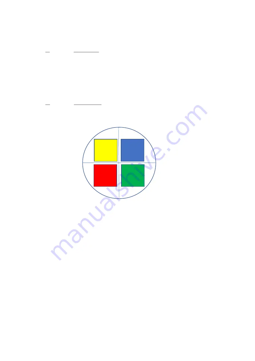
With all three calibration cubes in place, the four quadrants projected onto the piece of paper should be:
Figure 10: Images projected onto the paper over the camera aperture with all three cubes in place.
Note the quadrant colours are for illustrative purposes only and indicate the image wavelength from high to low
(Red > Yellow > Green > Blue).
4)
Obtaining a split image on your camera
As the four quadrants are now in the correct position, your imaging camera can now be attached to the
MultiSplit.
The silver knurled
camera mounting thread
on the output tube can be rotated to secure the camera, whilst also
ensuring any cables connected do not get tangled. Once the camera is fully screwed onto the c-mount, ensure
it is level and stable. The four small nylon tipped grub screws on this silver section can be tightened using the
1.5mm Allen key supplied to give extra rigidity.
Our
support jack
is highly recommended as an additional accessory to ensure the camera is fully supported on
the output port.
It’s useful at this stage to familiarise yourself with each of the four channels on your imaging camera. This can
be easily achieved using the shutter blanking plate supplied with each unit. This tool will block the light path in
the corresponding channel (see figure 14 and 15 for the auxiliary positions for each channel). The shutter
blanking plate can also be used during operation should one or more of the channels not be required.
TT
RR
TR
RT


