


1-28
Chapter 1: Product Introduction
•
System power LED (2-pin or 3-1 pin PLED)
The 2-pin or 3-1 pin connector is for the system power LED. Connect the chassis
power LED cable to this connector. The system power LED lights up when you turn on
the system power, and blinks when the system is in sleep mode.
•
Hard disk drive activity LED (2-pin HDD_LED)
This 2-pin connector is for the HDD Activity LED. Connect the HDD Activity LED cable
to this connector. The HDD LED lights up or flashes when data is read from or written
to the HDD.
•
System warning speaker (4-pin SPEAKER)
This 4-pin connector is for the chassis-mounted system warning speaker. The speaker
allows you to hear system beeps and warnings.
•
ATX power button/soft-off button (2-pin PWRSW)
This connector is for the system power button. Pressing the power button turns the
system on or puts the system in sleep or soft-off mode depending on the operating
system settings. Pressing the power switch for more than four seconds while the
system is ON turns the system OFF.
•
Reset button (2-pin RESET)
This 2-pin connector is for the chassis-mounted reset button for system reboot without
turning off the system power.
•
Chassis intrusion connector (2-pin CHASSIS)
This connector is for a chassis-mounted intrusion detection sensor or switch. Connect
one end of the chassis intrusion sensor or switch cable to this connector. The chassis
intrusion sensor or switch sends a high-level signal to this connector when a chassis
component is removed or replaced. The signal is then generated as a chassis intrusion
event.
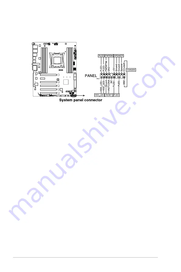
9.
System panel connector (20-3 pin PANEL)
This connector supports several chassis-mounted functions.
Содержание RenderCube XL
Страница 36: ...2 4 Chapter 2 Basic Installation Triangle mark Triangle mark...
Страница 38: ...2 6 Chapter 2 Basic Installation To remove a DIMM 2 1 4 DIMM installation...
Страница 40: ...2 8 Chapter 2 Basic Installation 2 1 6 SATA device connection OR OR...
Страница 43: ...RenderCube XL 2 11 To install HYPER M 2 x4 card The SSD card is purchased separately...


