background image


REQUIREMENTS/SPECIFICATIONS


Page 2-1


CHAPTER 2

REQUIREMENTS/SPECIFICATIONS


This chapter describes cable requirements, power requirements, and 
operating specifications for the TRXI. Be sure that you read this 
chapter before you install the TRXI. Your network must meet the 
requirements and conditions specified in this chapter to obtain 
satisfactory performance from this equipment. Failure to follow these 
guidelines could result in poor network performance.


2.1

CABLE SPECIFICATIONS


The basic concept of a token ring is a set of Trunk Coupling Units 
(TCUs) connected by trunk cabling. You can extend the trunk cabling 
by installing TPIMs into the TRXI’s RI/RO ports. TPIMs have 
embedded repeaters and provide trunk connections for UTP, STP, 
Multimode Fiber, and Single Mode Fiber cabling. 

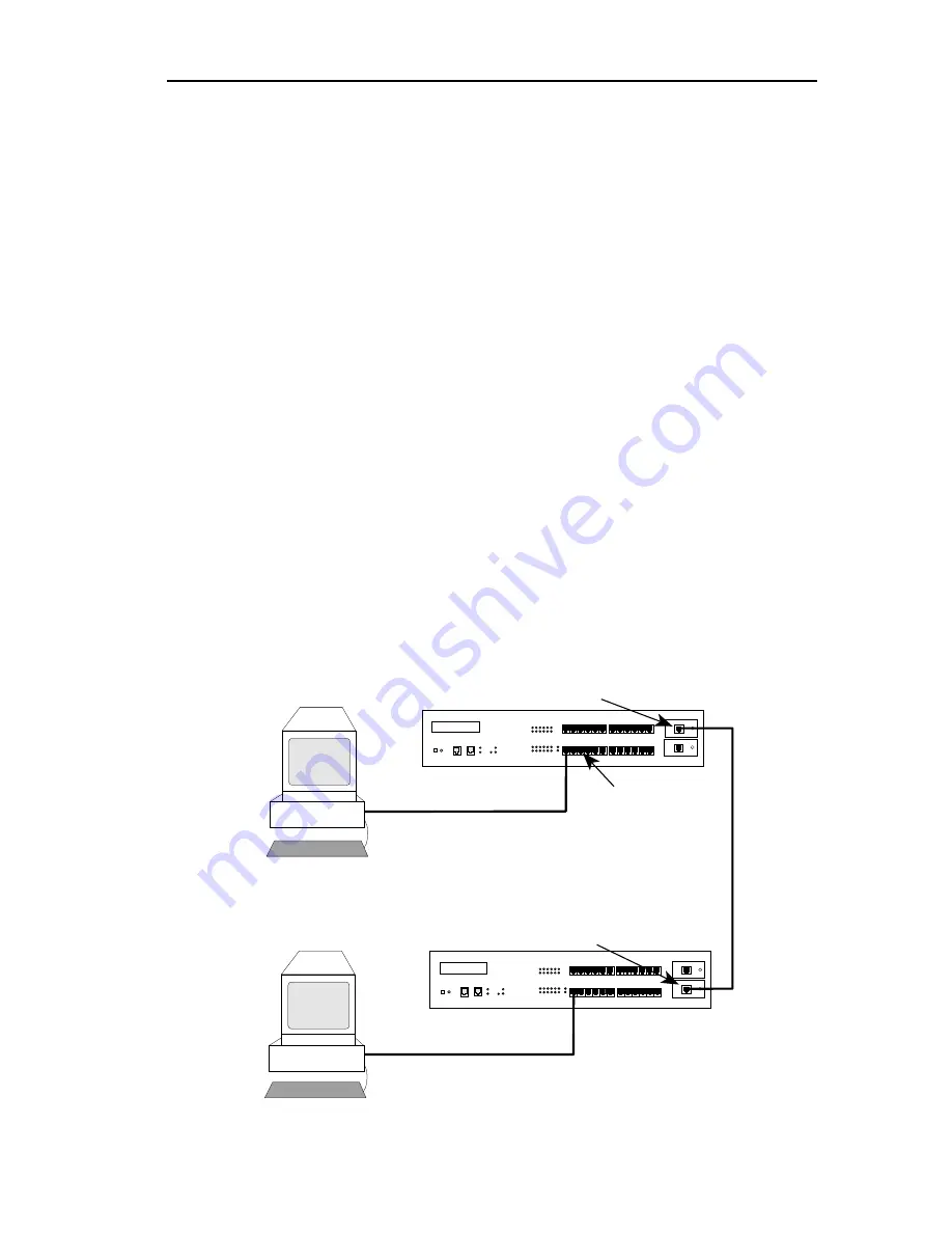
You attach stations to the TCU lobe ports with lobe cabling. Figure 2-1 
shows the various ports and cables.

Figure 2-1. TRXI Ports/Cables

Lobe Cabling

Trunk Cabling

Token Ring Station

TRXI-24 

TOKEN RING HUB 

WITH

 LANVIEW®

RI

RO

TRXI-24 

TOKEN RING HUB 

WITH

 LANVIEW®

RI

RO

Ring In TPIM

Ring Out TPIM

TCU Lobe Ports

Содержание TRXI-22

Страница 1: ...TRXI 22 TRXI 24 TRXI 42 AND TRXI 44 TOKEN RING INTELLIGENT HUB USER S GUIDE CABLETRON SYSTEMS P O Box 5005 Rochester NH 03867 0505 ...

Страница 2: ...NG OUT OF OR RELATED TO THIS MANUAL OR THE INFORMATION CONTAINED IN IT EVEN IF CABLETRON SYSTEMS HAS BEEN ADVISED OF KNOWN OR SHOULD HAVE KNOWN THE POSSIBILITY OF SUCH DAMAGES Copyright May 1994 by Cabletron Systems Inc P O Box 5005 Rochester NH 03867 0505 All Rights Reserved Printed in the United States of America Order Number 9030740 02 May 94 TRXI 22 TRXI 24 TRXI 42 TRXI 44 and TPIM are tradema...

Страница 3: ...s set out in the Radio Interference Regulations of the Canadian Department of Communications Le présent appareil numérique n émet pas de bruits radioélectriques dépassant les limites applicables aux appareils numériques de la class A prescrites dans le Règlement sur le brouillage radioélectrique édicté par le ministère des Communications du Canada CABLETRON SYSTEMS INC PROGRAM LICENSE AGREEMENT IM...

Страница 4: ...FORMATION SPECIAL INCIDENTAL CONSEQUENTIAL OR RELIANCE DAMAGES OR OTHER LOSS ARISING OUT OF THE USE OR INABILITY TO USE THIS CABLETRON PRODUCT EVEN IF CABLETRON HAS BEEN ADVISED OF THE POSSIBILITY OF SUCH DAMAGES BECAUSE SOME STATES DO NOT ALLOW THE EXCLUSION OR LIMITATION OF LIABILITY FOR CONSEQUENTIAL OR INCIDENTAL DAMAGES OR ON THE DURATION OR LIMITATION OF IMPLIED WARRANTEES IN SOME INSTANCES ...

Страница 5: ...ic Cable Specifications for the TPIM F2 2 7 2 1 5 Single Mode Fiber Optic Cable Specifications for the TPIM F3 2 8 2 2 CABLE RECOMMENDATIONS TROUBLESHOOTING 2 9 2 3 COM 1 COM 2 PORT SPECIFICATIONS 2 11 2 4 TPIM SPECIFICATIONS 2 12 2 5 GENERAL SPECIFICATIONS 2 17 CHAPTER 3 INSTALLATION 3 1 UNPACKING THE TRXI 3 1 3 2 ATTACHING THE STRAIN RELIEF BRACKET 3 1 3 3 INSTALLING THE TRXI 3 2 3 3 1 Rack Moun...

Страница 6: ...essages 4 4 4 3 2 Alarm Messages 4 5 4 3 3 Unsaved Initialization Messages 4 6 4 3 4 Saved System Messages 4 7 CHAPTER 5 LOCAL MANAGEMENT 5 1 MANAGEMENT TERMINAL REQUIREMENTS 5 2 5 1 1 Attaching the Management Terminal 5 2 5 1 2 Setting the Management Terminal Setup Parameters 5 3 5 1 3 Modem Cable Configuration and Setup 5 4 5 2 ACCESSING LOCAL MANAGEMENT 5 5 5 3 USING LOCAL MANAGEMENT 5 6 5 3 1 ...

Страница 7: ... manual s organization and content Chapter 1 Introduction outlines the contents of this manual and briefly describes features of the TRXI Chapter 2 Requirements Specifications describes cabling requirements network guidelines and TRXI operating specifications Chapter 3 Installation contains instructions for installing your TRXI and connecting it to the network using the various media types This ch...

Страница 8: ...he TRXI 22 24 42 and 44 are functionally identical with the exception of the TCU lobe ports Cabletron offers the following TRXI configurations TRXI 22 twelve RJ45 TCU lobe ports that support category 3 4 and 5 UTP cabling TRXI 24 twenty four RJ45 TCU lobe ports that support category 3 4 and 5 UTP cabling TRXI 42 twelve RJ45 TCU lobe ports that support IBM Type 1 2 6 or 9 STP cabling TRXI 44 twenty...

Страница 9: ...emulation software to the TRXI s COM 1 port LCD and Reset Button The LCD provides status information about the TRXI such as power up diagnostics revision levels serial numbers and error alerts The TRXI also has a Reset Button to initialize the processor Both the LCD and the Reset Button are located on the front panel of the TRXI Ring Speed Switch The Ring Speed Switch lets you select ring speeds o...

Страница 10: ...group Section Statistics rmon 1 Token Ring ML Stats Table statistics 2 History rmon 2 History Control Table history 1 Token Ring ML History Table history 3 Alarm rmon 3 Alarm Table Alarm 1 Event rmon 9 Event Table event 1 Log Table event 2 Token Ring rmon 10 Ring Station Control Table token ring 1 Ring Station Table token ring 2 Ring Station Order Table token ring 3 Ring Station Config Control Tab...

Страница 11: ...Protocol SNMP software Cabletron Systems offers the following remote management packages Cabletron Systems SPECTRUM Cabletron Systems Remote LANVIEW Windows Cabletron Systems Remote SPECTRUM Portable Management Applications The TRXI remote network management capabilities provide the necessary management tools for the TRXI to operate at its full capacity Your ability to set up parameters with netwo...

Страница 12: ... performance 2 1 CABLE SPECIFICATIONS The basic concept of a token ring is a set of Trunk Coupling Units TCUs connected by trunk cabling You can extend the trunk cabling by installing TPIMs into the TRXI s RI RO ports TPIMs have embedded repeaters and provide trunk connections for UTP STP Multimode Fiber and Single Mode Fiber cabling You attach stations to the TCU lobe ports with lobe cabling Figu...

Страница 13: ...nd Ringing voltages used in UTP telephone circuits could present a shock hazard and can damage token ring equipment when connected to token ring cabling The increased popularity and cost advantages of UTP cable have driven refinements to UTP cable design As a result better grades of UTP cable known as supergrade or level 4 are available that exhibit improved transmission characteristics These impr...

Страница 14: ... cabling you need a Type 3 Media Filter Cabletron Systems offers the following Type 3 Media Filters TRMF RJ45 UTP connector to 10 inch DB9 STP cable with LANVIEW TRMF 2 RJ45 UTP connector to DB9 STP connector Maximum Number of Stations When you use UTP lobe cabling anywhere on the ring the number of stations is limited to 100 stations at ring speeds of either 4 or 16 Mbps Table 2 2 UTP Maximum Lob...

Страница 15: ...STP lengths of 26 AWG stranded wire for data This type is used in patch panels or to connect devices to from wall jacks Attenuation for Type 6 cable is 3 2 x Type 1 cable 66 m of Type 6 100 meters of Type 1 IBM Type 9 Similar to Type 1 but uses 26 AWG solid wire Attenuation for Type 9 cable is 3 2 x Type 1 cable 66 m of Type 9 100 meters of Type 1 Attenuation and Impedance The attenuation values s...

Страница 16: ...ombined length of twice the longest trunk cable plus the longest lobe cable attached to the passive ring segment cannot exceed the Maximum Drive Distance Maximum Number of Stations When you use STP lobe cabling everywhere on the ring the TRXI can support up to 250 stations at ring speeds of either 4 or 16 Mbps Table 2 4 STP Maximum Lobe Lengths STP Cable Type Ring Speed 4 Mbps 16 Mbps IBM Types 1 ...

Страница 17: ...ling Installation 16 Mbps ring speed and 130 stations The building has 60 meters of Type 1 cable in the wall How much Type 6 cable is available to connect the repeater TCU port to the patch panel and the station to the local wall jack Type 6 can only go 2 3 the distance of Type 1 Solution 100 meters maximum cable length if only Type 1 cable is used 60 meters of Type 1 40 meters of Type 1 max lengt...

Страница 18: ...at is adjusted for an 850 nm wavelength This test verifies that the signal loss in a cable is within an acceptable level Table 2 6 shows the attenuation for each Multimode cable type Fiber Optic Budget When determining the maximum fiber optic cable length the fiber optic budget delay should be calculated and taken into consideration before fiber optic cable runs are incorporated in any network des...

Страница 19: ...n test set that is adjusted for a 1300 nm wavelength This test verifies that the signal loss in a cable is within an acceptable level of 10 dB or less for any given single mode fiber optic link Fiber Optic Budget Fiber optic budget is the combination of the optical loss due to the fiber optic cable in line splices and fiber optic connectors When determining the maximum fiber optic cable length the...

Страница 20: ... cabling away from potential noise sources motors switching equipment fluorescent lighting high amperage equipment or to ensure that the electrical wiring in the area is properly wired and grounded Temperature The attenuation of PVC insulated cable varies significantly with temperature Plenum rated cables are strongly recommended at temperatures greater than 40 C to ensure that cable attenuation r...

Страница 21: ...en ring signals should not be simultaneously used for applications which may impress high voltages greater that 5 volts with sharp rise or fall times since the noise coupling from such signals could directly cause errors on the token ring network For single telecommunications closet rings lobe lengths should not exceed 100 meters or 22 to 24 AWG wire from the attaching device and the TCU port When...

Страница 22: ...TRXI releases Figure 2 2 COM 1 COM 2 Ports Console The COM 1 port as default supports access to a Local Management Console The console supports a Digital Equipment Corporation VT 320 terminal or PC emulation of the VT 320 terminal Modem Both the COM 1 and COM 2 ports support access to Local Management using a modem UPS The COM 2 port supports an Uninterruptible Power Supply American Power Conversi...

Страница 23: ...Red TPIM T1 T2 T4 only No Link Autowrapped Off No Link Wrapped or Disabled The following sections describe each TPIM TPIM T1 The TPIM T1 is a female DB9 connector that supports STP cabling Figure 2 3 shows TPIM T1 pinouts for Ring Out and Ring In applications Figure 2 3 TPIM T1 Pinouts RING OUT 1 Transmit 2 Ground 3 5V at 250 mA 4 Ground 5 Receive 6 Transmit 7 Ground 8 Ground 9 Receive TPIM T1 LNK...

Страница 24: ...ing Out and Ring In applications Figure 2 5 TPIM T4 Pinouts RING OUT 1 Not Used 2 Not Used 3 Receive 4 Transmit 5 Transmit 6 Receive 7 Not Used 8 Not Used RING IN 1 Not Used 2 Not Used 3 Transmit 4 Receive 5 Receive 6 Transmit 7 Not Used 8 Not Used TPIM T2 LNK 1 2 3 4 5 6 7 8 RING OUT 1 Not Used 2 Not Used 3 Receive 4 Transmit 5 Transmit 6 Receive 7 Not Used 8 Not Used RING IN 1 Not Used 2 Not Use...

Страница 25: ... particular port If Power Levels are being measured with an Average Power Meter then 3 dBm must be added to the measurement to correctly compare those measured values to the values listed i e 30 5 dBm peak 33 5 dBm average Parameter Typical Worst Worst Case Typical Value Case Budget Budget Receive Sensitivity 30 5 dBm 28 0 dBm Peak Input Power 7 6 dBm 8 2 dBm Transmitter Power 50 125 µm fiber 13 0...

Страница 26: ...re increase multiply the typical coefficient 0 15 dBm by four and add the result to typical output power 4 x 0 15 dBm 16 4 17 0 TPIM F3 LNK RX TX Receive Sensitivity dBm Less Power More Power 40 35 30 25 20 15 10 5 0 Maximum Receive Input Power Transmitter Power At 25 C into 8 3 125µm fiber Minimum Sensitivity 30 0 Typical Sensitivity 31 0 Maximum Sensitivity 36 0 Maximum Receive Input 6 99 Typica...

Страница 27: ...or Rate Better than 10 10 Note The transmitter power levels given above are Peak Power Levels after optical overshoot You must use a Peak Power Meter to correctly compare the values given above to those measured on any particular port If you are measuring power levels with an Average Power Meter add 3 dBm to the average power measurement to correctly compare the average power values measured to th...

Страница 28: ...deable POWER SUPPLY REQUIREMENTS Note The TRXI has a universal power supply This unit allows you to use an input power from 85 to 264 VAC 47 63 Hz The power supply has two outputs of 5 volts and 12 volts The maximum output power is 125 watts and the minimum efficiency is 65 under all conditions of line at full load The minimum and maximum load current from each output is shown below Output Min Loa...

Страница 29: ...e EMC requirements of EN 50082 1 WARNING It is the responsibility of the person who sells the system to which the TRXI will be a part to ensure that the total system meets allowed limits of conducted and radiated emissions PHYSICAL Dimensions 2 8H x 17 0W x 13 5D inches 7 2H x 43 6W x 34 6D cm Weight Unit 7 95 pounds Shipping 11 95 pounds SERVICE MTBF 944 197 hours projected MTTR 0 5 hour ...

Страница 30: ... from the shipping box Slide the two foam end caps off the TRXI Remove the TRXI from the protective plastic bag and set it aside to prevent damage Visually inspect the TRXI If there are any signs of damage contact Cabletron Systems Technical Support immediately 3 2 ATTACHING THE STRAIN RELIEF BRACKET Attach the strain relief bracket to the front of the TRXI as follows 1 Locate the strain relief br...

Страница 31: ...h rack the following requirements must be met when selecting a location Note Be sure that the location selected is within reach of the network cabling An unrestricted free surface area at least 21 inches wide 18 inches deep and 6 inches high is needed A single phase 85 to 264 Vac 15A grounded power receptacle must be located within 7 feet of the site If a shelving unit is to be used it must be abl...

Страница 32: ...moved in step 1 attach the rack mounting brackets to each end of the TRXI Figure 3 2 Rack Mount Brackets Installation 3 With the mounting brackets installed position the TRXI between the vertical frame members of the 19 inch rack and fasten it securely with the mounting screws see Figure 3 3 Figure 3 3 Installing the TRXI in the Rack TRXI 24 TOKEN RING HUB WITH LANVIEW Screws 4 Wall Rack Mounting ...

Страница 33: ...bottom of the TRXI as shown in Figure 3 4 There are two brackets one for each side Figure 3 4 Wall Mounting the TRXI 2 Select the wall location for the TRXI within 7 feet of a power outlet Warning There is a potential SHOCK HAZARD if there is electrical wiring within the wall that interferes with drilling for pilot holes Select a wall location where drilling pilot holes for the Molly screws will n...

Страница 34: ...led 5 Tighten each of the anchor screws until the anchor expands holding the anchor firmly in the wall then remove the screws completely 6 Position the TRXI on the wall over the anchors and reinstall the four anchor screws to attach the TRXI to the wall as shown in Figure 3 4 Tighten the four anchor screws 3 3 3 Free Standing Installation For a free standing shelf or tabletop installation locate t...

Страница 35: ...ugh the air vent with a small screwdriver To change the ring speed 1 Turn off the TRXI 2 Place a small screwdriver through the TRXI s air vent to access the Ring Speed Switch 3 Use the screwdriver to slide the switch to the desired setting as shown in Figure 3 6 4 Turn on the TRXI 5 Check that the Ring Speed LED indicates the correct setting Figure 3 6 The Ring Speed Switch DISPLAY TRXI 24 TOKEN R...

Страница 36: ...et Switch To restore TRXI parameters to the factory defaults 1 Change the state of this switch i e move the switch from one position to another 2 Press the TRXI s Reset button You can now use the factory default settings or re enter your own parameters The TRXI stores these parameters in NVRAM during normal operation and during power down and they remain there until you change the switch again Cau...

Страница 37: ...shielded RJ45 connectors that support UTP cabling To connect a UTP segment from the TRXI to a station supporting STP cabling you need a Type 3 Media Filter available from Cabletron Systems TRMF TRMF 2 The TRXI 42 44 network lobe ports consist of shielded RJ45 connectors that support STP cabling Shielded patch cables that adapt a shielded RJ45 to a data connector MIC are available from Cabletron Sy...

Страница 38: ...k WIRING CLOSET OFFICE Token Ring Station Token Ring Network Interface Card Wall Jack UTP Lobe Cable WALL TRXI 24 TRXI 24 TOKEN RING HUB WITH LANVIEW RI RO TRMF STP to UTP Type 3 Media Filter TRXI 24 TOKEN RING HUB WITH LANVIEW RI RO Patch Panel MIC Data Connector WIRING CLOSET OFFICE Token Ring Station Token Ring Network Interface Card Wall Jack STP Lobe Cable WALL TRXI 44 ...

Страница 39: ...he following steps until it is a Check that the device at the other end of the twisted pair segment is on and the network interface driver is initialized b Verify that the RJ45 connector on the twisted pair segment has the proper pinouts c Check the cable for continuity d Check that the twisted pair connection meets dB loss and cable specifications outlined in Chapter 2 e Check Local Management to...

Страница 40: ...t The following sections explain how to set the Phantom Switch set the RI RO Switch install the TPIM to the TRXI and attach segments to the TPIM Prior to connecting trunk cabling to the TPIMs check the connectors for proper pinouts Table 3 1 provides a cross reference of pinouts for TPIMs used for Ring In or Ring Out applications Table 3 1 Pinout Cross Reference for TPIMs Signal TPIM T2 T4 RJ45 Ri...

Страница 41: ...ting at this time Note If the switch locations on your TPIM do not match the locations illustrated in Figure 3 11 refer to the TPIM Reference Card included with the TPIM The TPIM Reference Card outlines the current switch locations and settings If you have any questions call Cabletron Systems Technical Support Figure 3 11 The Phantom and RI RO Switches Top View TPIM T1 TPIM T2 TPIM T4 Phantom Swit...

Страница 42: ...plate of the RI RO port on the TRXI 2 If you are replacing a TPIM remove the mounting screw and pull the TPIM straight out from the TRXI 3 Slide the new TPIM into place as shown in Figure 3 12 4 Ensure the connectors on the rear of the module and on the inside of the TRXI mate properly 5 Reinstall the mounting screw Figure 3 12 Installing a TPIM RI RO 6 5 4 3 2 1 18 17 16 15 14 13 TPIM T1 LNK TPIM...

Страница 43: ...Check that the LNK LED on the TPIM lights green If the LED lights red is not lit perform each of the following steps until it is a Check that the device at the other end of the segment is on b Verify that the DB9 is pinned properly c Check the cable for continuity d Check that the twisted pair connection meets dB loss and cable specifications outlined in Chapter 2 e Check that the port is enabled ...

Страница 44: ...egment into the RJ45 port on the TPIM as shown in Figure 3 14 Figure 3 14 The TPIM T2 T4 2 Check that the LNK LED on the TPIM lights green If the LED lights red or is not lit perform each of the following steps until it is a Check that the device at the other end of the segment is on b Verify that the RJ45 is pinned properly c Check the cable for continuity d Check that the twisted pair connection...

Страница 45: ...the applicable port on the module will go to RX of the other fiber optic device The Receive strand of the applicable port on the module will be connected to the Transmit port of the fiber optic device For example RX of the applicable port on the module will go to TX of the other fiber optic device It is recommended that you label the fiber optic cable to indicate which fiber is Receive and which i...

Страница 46: ...t port labeled TX on the module 4 At the other end of the fiber optic cable attach the fiber labeled 1 to the transmit port of the device 5 Attach the fiber labeled 2 to the receive port 6 Check that the LNK LED on the TPIM lights green If the LED does not light perform each of the following steps until it is a Check that the power is turned on for the device at the other end of the link b Verify ...

Страница 47: ...s Technical Support 3 9 FINISHING THE INSTALLATION The TRXI is now ready for operation Before placing the network into service test the installation thoroughly making sure that all stations are able to be addressed and that the TRXI and all stations are indicating normal operation Ensure that the networking software is configured properly to match the installed network If you encounter errors or a...

Страница 48: ...ion b Verify the pinouts for every connection c Check the cable conductors for continuity Cable testers are available for this task d Check that cable connections at patch panels and wall plates are secure 2 Check the network ring speed a Check the Ring Speed LED Ensure the ring speed matches the station and cable specifications explained in Chapter 2 b Be sure that all devices in the ring network...

Страница 49: ...ff Green Solid Green Blinking Green Solid Red Solid Off Green Solid Yellow Solid Off Green Flashing Red Flashing Off Green Solid Red Solid Off Green Flashing Green Blinking Red Solid DEFINITION Port Enable No Link or Port Disable No Link Port Enable Link Port Disable Link TPIM Inserted TPIM Not Inserted No Power Power 16 Mbps Ring Speed 4 Mbps Ring Speed Good Frames Beacon Frames No Activity Manag...

Страница 50: ...n levels Hardware MAC address IP address Error alerts The LCD presents four types of messages Static System Messages Saved Alarm Messages Unsaved Initialization Messages and Saved System Messages The following sections describe each message Figure 4 2 LCD Display LCD DISPLAY TRXI 24 TOKEN RING HUB WITH LANVIEW 24 23 COM 2 COM 1 18 17 16 15 14 13 6 5 4 3 2 1 24 23 22 21 20 19 12 11 10 9 8 7 RO RI P...

Страница 51: ... changed through Local Management MAC Address Displays the Hardware 0000B8xxxxxx or MAC address RAM Image Displays the revision number of the Rev xx xx xx Flash EEPROM Boot PROM Displays the revision number of the Rev xx xx xx internal Boot PROM Flash Programmed Displays the number of times the xx Times the Flash EEPROM has been programmed COM 1 Displays the current baud rate Baud Rate xxxxxx of t...

Страница 52: ...ork port or TPIM turned off Disabled via Local or Remote Management Port xxxxxx Network port or TPIM turned on Enabled via Local or Remote Management Port xx Violation Indicates unauthorized access attempt at network lobe ports Ring Beaconing Indicates a station is attempting to recover from a hardware problem on the ring Beacon Recovered Indicates the ring has recovered from a beaconing situation...

Страница 53: ... SCC Error Cabletron Cabletron Bit Swap Failure Console SCC Error Cabletron Cabletron LDRAM Failure 82C54 Failure Cabletron Eagle Failure Normal Unsaved Initialization Messages Cabletron Cabletron Cabletron Hardware Init Boot From Flash Eagle Test Cabletron Cabletron Cabletron BOOTP Discovery RARP Req State Bit Swap Test Cabletron Cabletron TFTP Req State TFTP in Progress Cabletron Cabletron TFTP ...

Страница 54: ...nter the Saved Alarm Messages queue While in the Alarm Messages queue press the Display button and hold for five seconds You can scroll through each message by pressing the Display button If you do not press the Display button for ten seconds the LCD defaults to the product name Displayed Message TFTP Host TFTP File xxx xxx xxx xxx xxxxxxxxxxxxxxxx Last TFTP Host Last TFTP File xxx xxx xxx xxx xxx...

Страница 55: ... token ring network using the Ring Security feature assign an IP address and subnet mask set interface parameters for both serial ports Local Management Console Serial Line Internet Protocol SLIP Uninterruptible Power Supply proxy UPS or Modem control password access to the TRXI through the community names established in the Community Names Table designate which Network Management Workstations rec...

Страница 56: ...it with the TRXI This kit includes a UTP console cable with RJ45 connectors on each end It also provides adapters for DB9 or DB25 connections Refer to the RJ45 Cable Kit Instruction Sheet for adapter pinouts and additional instructions To attach the management terminal to the TRXI s COM 1 port 1 Attach the male RJ45 connector to the COM 1 port of the TRXI as shown in Figure 5 1 2 Attach the female...

Страница 57: ...etup Parameters MENU FUNCTION SELECTION Display Setup Columns 80 Columns Controls Interpret Controls Auto Wrap No Auto Wrap Test Cursor Cursor General Setup Mode 7 Bit Control Cursor Keys Normal Cursor Keys Communications Setup Transmit Transmit 9600 Receive Receive Transmit XOFF any option Bits Parity 8 Bits No Parity Stop Bit 1 Stop Bit Local Echo No Local Echo Port DEC 423 Data Leads Only Trans...

Страница 58: ...ss Local Management proceed as follows 1 Turn the modem on The modem must be set for Auto Answer and Data Carrier Detect must be active Refer to your modem s user manual for operating instructions 2 Call the modem The TRXI Password screen appears when you establish a connection RJ45 COM 2 Port Pin 1 RJ45 COM 2 PORT 1 4 5 2 3 7 TRANSMIT RECEIVE RECEIVE TRANSMIT SIGNAL GROUND SIGNAL GROUND RJ45 TO 2...

Страница 59: ...mmunity names specified in the Community Name Table Access to certain Local Management capabilities depends on the degree of access accorded that community name See Section 5 3 2 for more information about community names 3 If your password is valid the Main Menu screen shown in Figure 5 4 appears If your password is not valid the cursor returns to the beginning of the password field Cabletron Sys...

Страница 60: ...ions explain how to select and use each of the Local Management options Figure 5 4 Local Management Menu Screen DEVICE STATUS CHASSIS STATUS VIEW COMPONENT STATUS VIEW RMON VIEW RETURN SYSTEM LEVEL SNMP COMMUNITY NAMES SNMP TRAPS RING SECURITY FLASH DOWNLOAD RETURN DEVICE SETUP DEVICE SETUP DEVICE STATUS DEVICE STATISTICS MIB NAVIGATOR SNMP TOOL EXIT LM MAIN MENU TRXI LOCAL MANAGEMENT Flash Image ...

Страница 61: ...t the RETURN command at the bottom of the screen 2 Press Return Local Management returns to the associated Menu screen Exiting Your Local Management Session To exit your Local Management session 1 Use the arrow keys to highlight the RETURN command at the bottom of the screen 2 Repeat Step 1 until you arrive at the Main Menu screen 3 Use the arrow keys to highlight the EXIT LM command at the bottom...

Страница 62: ...eld on the System Level screen and instructions for using them System Date Displays the current date System Time Displays the current time IP Address Displays the IP Address of the SNMP agent Subnet Mask Displays the Subnet Mask of the SNMP agent TRXI LOCAL MANAGEMENT Flash Image Version X XX XX SYSTEM LEVEL System Date 06 26 94 System Time 14 00 00 IPAddress Subnet Mask SNMPAgent 000 000 000 000 ...

Страница 63: ...le Beacon Recovery Enables Beacon Recovery MAC Address Displays the physical hardware address Setting the System Date To set the System date 1 Use the arrow keys to highlight the System Date field 2 Enter the date into the field in a MM DD YY format 3 Press Return If the format not valid the message INVALID DATE appears Re enter the date using the correct format 4 If the format is correct use the ...

Страница 64: ...pears on the screen indicating that your changes have been saved to memory Setting the IP Address To set the IP Address 1 Use the arrow keys to highlight the IP Address field 2 Enter the IP Address into the field The format for this entry is XXX XXX XXX XXX with values of XXX ranging from 0 255 3 Press Return If the format is not valid the message INVALID IP FORMAT appears Re enter the IP Address ...

Страница 65: ...keys to highlight the Subnet Mask field 2 Press Return to clear the field 3 Enter the Subnet Mask into the field The format for this entry is XXX XXX XXX XXX with values of XXX ranging from 0 255 4 Press Return If the format is not valid the INVALID IP FORMAT message appears Re enter the Subnet Mask using the correct format 5 If the format is correct use the arrow keys to highlight the SAVE comman...

Страница 66: ...m Yes to No 3 Select Yes to clear NVRAM or No to escape the field 4 Use the arrow keys to highlight the SAVE command 5 Press Return The SAVED message appears on the screen indicating that your changes have been saved to memory Setting the Enable Beacon Recovery Field To set the Enable Beacon Recovery field 1 Use the arrow keys to highlight the Enable Beacon Recovery field 2 Press Return to toggle ...

Страница 67: ...ce IP address and the community names Caution Community Names are passwords to Local Management Remember your Community Name Local Management passwords accorded Read Only and Read Write access privileges are not allowed editing capabilities to some fields In this case the message AUTHORIZATION PROHIBITS ACCESS appears Figure 5 6 shows the SNMP Community Names screen Figure 5 6 SNMP Community Names...

Страница 68: ...Read Write or Super User Read Write This allows you to read and write to Local Management fields excluding IP Address Subnet Mask and Community Names and Ring Security Super User This allows read write access to all modifiable parameters including Community Names IP Addresses Traps Ring Security and SNMP objects Editing the Community Name Field To edit the Community Name field 1 Use the arrow keys...

Страница 69: ...em Trap Destination Indicates the IP Address of the workstation that will receive trap alarms from the TRXI Trap Community Name Displays the user defined name of the SNMP Compliant Network Management Workstations to receive trap alarms from the TRXI Enable Traps Enables the transmission of SNMP trap messages TRXI LOCAL MANAGEMENT Flash Image Version X XX XX SNMP TRAPS Trap Destination Trap Communi...

Страница 70: ...rrow keys to highlight the Trap Community Name field 4 Enter the community name of the device then press Return If you press Return without entering a community name the field defaults to CR 5 Use the arrow keys to highlight the Enable Traps field 6 Enter Y yes to send alarms from the TRXI to the workstation or N no to prevent alarms from being sent 7 Use the arrow keys to highlight the SAVE comma...

Страница 71: ...ed list and automatically re enables ring security Figure 5 8 Ring Security Screen You can append the allowed list by temporarily disabling ring security then re enabling it using the Alarms Only feature The TRXI acts as the Ring Security Monitor for the ring and provides security for the entire ring Note You should enable the Ring Security feature on only one TRXI per token ring You can select tw...

Страница 72: ... screen section This ensures that trap alarms generated by ring security arrive at the appropriate destination Station Address This field lists the MAC address of each station on the ring security allowed list This field can lists up to 250 MAC addresses on 22 local management screens Stn Edit The Station Edit command lets you add or delete stations from the allowed list Use the Stn Edit command f...

Страница 73: ... mode ring security sends a Remove MAC Frame Command to new stations attempting to enter the ring and a trap alarm to the NMS informing it of the action taken The Remove MAC Frame Command tries to automatically remove the station from the ring If it cannot remove the station from the ring after three attempts it sends a trap alarm to the NMS informing it that the station could not be removed SAVE ...

Страница 74: ...ars at the top of the screen 5 To view the allowed list you must refresh the Ring Security screen by exiting then re entering the screen Adding Stations to the Station Address Allowed List To add stations one at a time to the Station Address allowed list 1 Use the arrow keys to highlight the Stn Edit field 2 Press Return to clear the field 3 Enter the MAC address of the station you want to add in ...

Страница 75: ... EXECUTE command 7 Press Return The station s MAC address is deleted Note You must set ring security to the Alarm Remove mode to effectively delete a station from the allowed list and keep it off the ring If you delete a station from the allowed list while in the Alarm Only mode the station can re enter the ring and its Mac address will reappear in the allowed list Changing the Ring Security Mode ...

Страница 76: ...statistic count Delta Total of statistics beginning from the last screen refresh Total Total of statistics beginning from the last power up Interface Displays the network interface This field is always 1 Frames Received 0 KBytes Received 0 Errors Received 0 Beacon States 0 Ring Purges 0 Active Monitor Changes 0 TRXI LOCAL MANAGEMENT Flash Image Version X XX XX DEVICE STATISTICS TOTAL INTERFACE 1 L...

Страница 77: ...by the active monitor Active Monitor Changes Displays the number of times a different station has been active monitor ISOLATING ERRORS Isolating Errors are soft ring errors that report the domain of a fault that is you can isolate the fault s region to the transmitting adapter the receiving adapter and the components cabling and wiring concentrators between the two Line Errors Displays the total l...

Страница 78: ... incorrect NAUN address Abort Transmit Errors Displays the total abort delimiter frames transmitted by a station This indicates that either the reporting node has detected an error on itself or there is an error with its NAUN or the cabling and wiring hubs between them Internal Errors Displays the total internal errors detected by the adapter s hardware and or firmware These errors cause the adapt...

Страница 79: ...has detected a beacon frame Lobe Fail Indicates that a station failed the lobe self test when it attempted to insert into the ring Ring Number Displays the number of rings on the network Stations on a Ring Displays the number of stations inserted into the ring Ports Enabled Displays the number of network lobe ports enabled Ring Speed Displays the ring speed of the TRXI as either 4 Mb s or 16 Mb s ...

Страница 80: ... occurred or sees a recirculating frame or token The active monitor is responsible for purging the ring and issuing a new token Frequency Errors Displays the total number of frequency errors This indicates that the frequency of the incoming signal deviates excessively from the adapter s onboard crystal oscillator It could indicate an error in this node s oscillator the active monitor or any node i...

Страница 81: ...s field at the top of the screen Only the unused counter modes appear at the bottom of the screen 2 Press the Return key The selected counter mode appears at the top of the screen Setting the Refresh Field To set the Refresh field 1 Use the arrow keys to highlight the REFRESH99sec field at the bottom of the screen 2 Press the Shift and keys to increment the time interval or the key to decrease the...

Страница 82: ... and instructions for using them Port Status Displays the port status as Administrative or Operational Temp Displays the hub temperature as Normal Warm or Hot Mode Displays the current status view as Operational or Administrative Enable All Ports Enables all TRXI ports TRXI LOCAL MANAGEMENT Flash Image Version X XX XX CHASSIS STATUS VIEW PORT STATUS ADMIN TEMP NORMAL 24 23 22 21 20 19 18 17 16 15 ...

Страница 83: ...ys to highlight Enable All Ports 2 Press Return to Enable all the TRXI ports Setting the Operational Administrative Mode Option To set the Operational Administrative Mode option 1 Use the arrow keys to highlight Operational or Administrative 2 Press Return to select Operational or Administrative The selected mode appears in the Mode field Setting the Refresh Field To set the Refresh field 1 Use th...

Страница 84: ...o set the Refresh field 1 Use the arrow keys to highlight the REFRESH99sec field at the bottom of the screen 2 Press the Shift and keys to increment the time interval or the key to decrease the time interval 3 Press the Return key to save your changes TRXI LOCAL MANAGEMENT Flash Image Version X XX XX COMPONENT STATUS VIEW COMPONENT NAME TRXI Chassis MGR TRXI LIM Network 1 TRXI Protocol Stack TRXI ...

Страница 85: ...bout object identifiers OIDs edit configurable OIDs view OIDs sequentially from the originally requested OID To access the SNMP Tools Screen from the Features Selection Screen use the arrow keys to highlight the SNMP Tool Support option then press the Return key The SNMP Tools Screen Figure 5 12 appears Figure 5 12 SNMP Tools Screen The following describes the SNMP Tools Screen fields and commands...

Страница 86: ...er specified object identifier Leaves are objects or instances of objects After initializing a walk you see the following categories for each entry Specified OID identifies the number tag for that OID Size gives the number of bytes required to store the object Data Type gives the object s variable type e g int integer Data Value displays what the object identifier represents RECALL OID Recalls fro...

Страница 87: ...OID element in the chCompName group indicates its match in the chCompSUCommStr group In order to access a specific MIB s components you must set the appropriate MIB password in the COMMUNITY NAME field Note The default Super User password public allows you to access all MIB components To change the SNMP Tools screen COMMUNITY NAME field you must have Super User access to Local Management To set th...

Страница 88: ...key If there is no instance of that OID the TRXI displays MIB_NO_INSTANCE Otherwise the TRXI displays that OID s data type length and value To get the next OID 1 Highlight GETNEXT using the arrow keys 2 Press the Return key GETNEXT OID F9 appears 3 Enter the OID 4 Press the Return key If that OID does not exist the TRXI displays MIB_NO_INSTANCE Otherwise the TRXI displays that OID s data type leng...

Страница 89: ...g a String SNMP tools requests the kind of data you plan to enter HEX or ASCII In this example choose ASCII 6 Press the Return key The TRXI displays SNMP OID DATA 7 Enter the Data or value of the OID Type in a sysContact This OID allows for a String of up to 12 characters 8 Press the Return key If the TRXI accepts the entry it displays SET OPERATION CODE XXXX OK otherwise an error message appears ...

Страница 90: ... the walk or wait for MIB WALK COMPLETED to appear on the screen To cycle through 1 Highlight CYCLES using the arrow keys 2 Press the Return key ENTER CYCLE COUNT appears 3 Enter the number of OID cycles that you want to scroll through 4 Press the Return key ENTER CYCLE DELAY appears 5 Enter the delay that you want in seconds between get next requests 6 Press the Return key INITIAL OID F9 appears ...

Страница 91: ...MENT Page 5 37 4 Press the Return key The initial OID details including its size data type and data value appear 5 Highlight STEP using the arrow keys 6 Press the Return key to page through the MIB to the next OID ...

Страница 92: ... Anwendung des Geraetes geeignet und der zum Benuetzen im Lande der Anwendung anerkannt ist SPANISH El cable principal de la red eléctrica utilizado con este equipo debe tener 2 conductores y 1 toma de tierra con un mínimo de 0 75 mm2 cada uno y necesita tener un aparato de acoplamiento standard IEC en un extremo y un enchufe para el cable principal de la red eléctrica en el otro extremo lo cual s...

Отзывы: