22
22
5.2
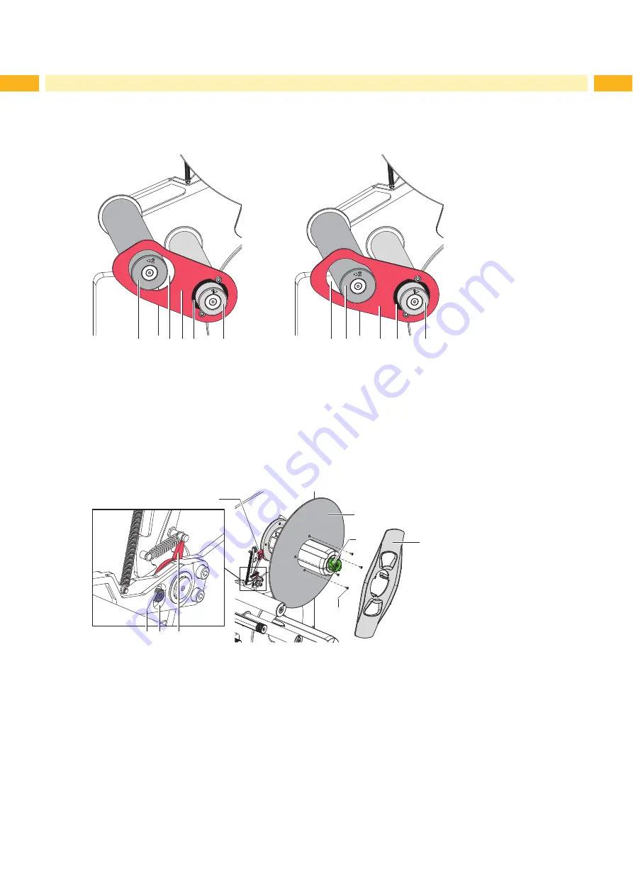
Adjusting the Brake at the Label Unwinder
The brake (9) at the label unwinder is switched on and off by the movement of the swing arm (1). The correct
adjustment of the switching point guarantees an accurate label transport and a high positioning accuracy of the
peeled labels.
1
2 3 4
5
1
2
3
4
5
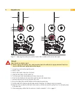
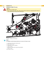
Figure 20 Checking the switching point of the brake
1. Press down the swing arm with the guide roller (1).
2. Push the collar (4) of the gauge (3) onto the guide roller (5) and insert the guide roller (1) into the slot hole (2).
3. Release the swing arm. The guide roller (1) moves to the upper end of the slot hole (2) (Figure 20 left side).
Requirement A:
In that position the unwinder must be blocked by the brake.
4. Press down the swing arm so that the guide roller (1) touches the lower end of the slot hole (2)
(Figure 20 right side).
Requirement B:
In that position the brake must release the label unwinder.
12/4x
11
10
6 7
8
9
13
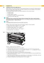
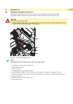
Figure 21 Adjusting the switching point of the brake
If one of the requirements will not be achieved the switching point must be re-adjusted :
5. Turn the knurled knob (11) clockwise and remove the margin stop (13) from the unwinder.
6. Loosen 4 screws (12) remove the wall spacer (10).
7. Loosen screw (6) and move it inside the slot hole (7). That way the initial position of the lever (8) will be altered :
•
Requirement A not achieved : Move the screw upwards inside the slot hole
•
Requirement B not achieved : Move the screw downwards inside the slot hole
8. Tighten screw (6) and repeat the check with the gauge (3).
9. If necessary repeat the adjustment.
10. If the switching point cannot be adjusted to achieve requirement A (blocking), replace the brake shoe
11. Complete the unwinder.
Содержание Hermes C 6L
Страница 1: ...Made in Germany Service Manual Hermes C Label Printer ...
Страница 33: ...33 7 Block Diagram Figure 34 Block diagram Hermes C ...
Страница 34: ...34 34 8 Layout Diagram CPU Figure 35 Layout diagram PCB CPU components side ...
Страница 35: ...35 Figure 36 Layout diagram PCB CPU soldering side 8 Layout Diagram CPU ...

