background image

GasAlertMicroClip 
Quick Reference Guide 

16 

This equipment has been tested and found to comply with the 
limits for a Class B digital device, pursuant to Part 15 of the 
FCC Rules and ICES-003 Canadian EMI requirements. These 
limits are designed to provide reasonable protection against 
harmful interference in a residential installation. This equipment 
generates, uses and can radiate radio frequency energy and, if 
not installed and used in accordance with the instructions, may 
cause harmful interference to radio communications. However, 
there is no guarantee that interference will not occur in a 
particular installation. If this equipment does cause harmful 
interference to radio or television reception, which can be 
determined by turning the equipment off and on, the user is 
encouraged to try to correct the interference by one or more of 
the following measures: 


Reorient or relocate the receiving antenna. 


Increase the separation between the equipment and 
receiver. 


Connect the equipment into an outlet on a circuit 
different from that to which the receiver is connected. 


Consult the dealer or an experienced radio/TV technician 
for help. 


Содержание GasAlertMicroClip

Страница 1: ......

Страница 2: ...ations of BW b the buyer promptly notifying BW of any defect and if required promptly making the product available for correction No goods shall be returned to BW until receipt by the buyer of shippin...

Страница 3: ...uages are displayed on the detector and in the corresponding Quick Reference Guide Safety Information Read First Use the detector only as specified in this guide otherwise the protection provided by t...

Страница 4: ...at the audible and visual alarms are activated Calibrate if the readings are not within the specified limits Caution High off scale readings may indicate an explosive concentration Any rapid up scalin...

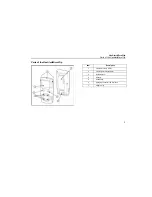
Страница 5: ...ts of the GasAlertMicroClip Parts of the GasAlertMicroClip Item Description 1 Visual alarm bars LED 2 Liquid crystal display LCD 3 Audible alarm 4 Sensors 5 Pushbutton 6 Charging connector IR interfac...

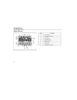
Страница 6: ...ck Reference Guide Display Elements Item Description 1 Alarm condition 2 Automatically span sensor 3 Gas cylinder 4 Gas identifier bars 5 Battery life indicator 6 Stealth mode 7 Numeric value 8 Automa...

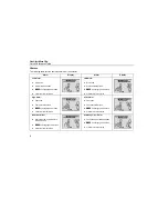
Страница 7: ...To clear the TWA STEL and MAX readings press C when the LCD displays RESET To initiate calibration press and hold C as the detector executes the OFF countdown and continue to hold C as the LCD briefly...

Страница 8: ...tector completes the span 2 The detector then activates again and performs the CAL countdown Continue to hold C until the countdown is complete to enter calibration 5 The LCD then displays CAL DUE It...

Страница 9: ...GasAlertMicroClip Attach the Gas Cylinder to the Detector Attach the Gas Cylinder to the Detector 7...

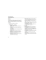
Страница 10: ...ash L and target gas bar flash Vibrator alarm activates High Alarm Fast siren Fast alternating flash L and target gas bar flash Vibrator alarm activates STEL Alarm Fast siren Fast alternating flash L...

Страница 11: ...ting access the latching alarms option in the GasAlertMicroClip Soft Tools software Local regulations may require a latching alarm If the detector is in stealth mode it only vibrates in alarm mode the...

Страница 12: ...sensors only STEL Alarm The short term exposure limit STEL alarm setpoint toxic sensors only STEL Interval Changes the short term exposure limit 5 15 minutes applicable to toxic sensors only Auto Zero...

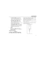
Страница 13: ...ration upon start up The detector must be charged in a non hazardous atmosphere of 0 C 45 C 32 F 113 F To reach full battery capacity allow the battery to fully charge and fully discharge three times...

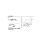
Страница 14: ...ular intervals Keep an operations log of all maintenance bump checks calibrations and alarm events Clean the exterior with a soft damp cloth Do not use solvents soaps or polishes Replacing a Sensor or...

Страница 15: ...PCB and remove the PCB Note Ensure the battery does not get damaged once the PCB is removed 4 Remove the old sensor filter or slide pull out the old sensor s 5 Insert a new sensor filter or sensor s...

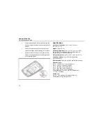
Страница 16: ...bustible sensor with 5 accuracy Ensure the rib on the interior of the rear shell fits between the battery pack and the PCB as shown in the following figure Storage temperature 40 C to 50 C 40 F to 122...

Страница 17: ...ce bump bump interval bump due lock stealth mode IR stealth mode language selection enable disable automatic oxygen calibration enable disable auto zero at start up set alarm setpoints set span concen...

Страница 18: ...ns may cause harmful interference to radio communications However there is no guarantee that interference will not occur in a particular installation If this equipment does cause harmful interference...

Страница 19: ...hnologies 2006 all rights reserved Printed in Canada All product names are trademarks of their respective companies Quick Reference Guide GasAlertMicroClip H2S CO O2 Combustibles 1 2 3 and 4 Gas Detec...

Страница 20: ...confirm their ability to respond to gas by expos ing the detector to a gas concentration that exceeds the alarm setpoints Manually verify that the audible and visual alarms are activated If any senso...

Отзывы: