


SERVICE
CAUTION
To avoid possible injury, observe the following
safety rules WHEN SERVICING the backhoe:
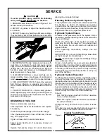
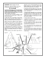
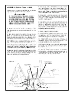
1. ENGAGE safety locks as shown in Figures 1 & 3
before servicing the backhoe.
2. DO NOT oil, grease or adjust the backhoe while it
is in motion.
3. DO NOT change any backhoe relief valve settings.
They are factory set for best performance and safety.
4. ESCAPING FLUID under pressure can have suffi-
cient force to penetrate the skin and cause serious
injury. Be sure to relieve all pressure before discon-
necting lines. Be sure all connections are tight and
that lines, pipes and hoses are not damaged before
applying pressure to the system.
5. FLUID ESCAPING from a very small hole can be
almost invisible. Use a small piece of cardboard or
wood - not your hands - to search for suspected leaks.
6. SEE A DOCTOR AT ONCE if injured by escaping
fluid. Serious infection or gangrene can develop if
proper medical treatment is not administered immedi-
ately.
7. PROTECT YOUR EYES - Wear safety glasses.
Guard against injury when driving connecting pins or
performing any repair in which particles can chip from
work piece or striking tool.
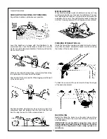
BEGINNING OF SEASON
Remove all protective covering.
Check hydraulic hoses for deterioration and replace,
if necessary.
Lubricate all grease fittings and oil handle linkage.
Check hydraulic system for loss of fluid and, if neces-
sary, fill to proper level.
Tighten all loose bolts, nuts and setscrews.
Inspect bucket teeth and, if necessary, sharpen or
replace them.
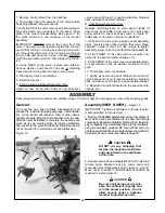
Operate the backhoe slowly for a short time before
Bleeding Backhoe Hydraulic System
If the hydraulic hoses have been disconnected from
the backhoe or tractor, all trapped air must be
removed after the hoses are connected. Start tractor
engine and operate backhoe through all movements
fully, several times, to purge the system of air.
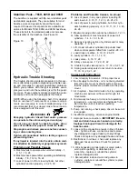
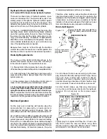
Hydraulic System Hoses
Oil leaks in the pressure side of the system can be
located by carefully inspecting the external area of the
hoses and fittings.
Check the return side of the system for leaks by
examining the oil in the reservoir. If air is being drawn
into the system, the oil will contain air bubbles and
appear to foam.
When tightening connections, always use two
wrenches.
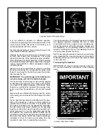
IMPORTANT: Do not over-tighten fittings. Make them
just tight enough to eliminate leaks.
NEVER use teflon tape on pipe thread fittings. Always
use a paste-type sealer.
Hoses on any backhoe are very severely worked and
will fail in time. Examine them regularly and replace
any that show signs of failure. Pay careful attention to
the routing of hoses so they can move fully and freely
without kinking, and cannot be pinched or cut by any
part of the backhoe.
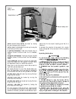
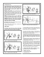
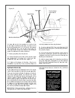
Hydraulic System Reservoir
On PTO pump contained systems, maintain the reser-
voir oil at the proper level by looking at the dipstick. The
dipstick/breather cap is located directly behind the right
hand foot pad on the backhoe. When checking oil level,
the backhoe should be extended to full reach with the
bucket rolled back and resting on the ground. All cylin-
ders are retracted except for the boom cylinder. Do not
overfill; oil may be forced out of the breather cap.
Fill with:
SAE 10W40 engine oil with API “SF/SG” classifica-
tion in northern climates.
SAE 40W engine oil with API “SF/SG” classification
in southern climates.
Change oil every 200 hours or more often if neces-
sary.
If the tractor system supplies the hydraulic power, ser-
vice according to the tractor instruction manual.
Figure 5
14
placing the unit under full load.
Bucket Tooth Points