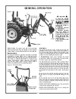
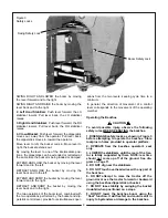
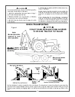
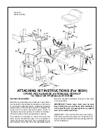
background image

General Operations

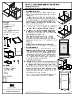
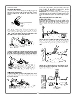
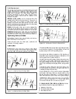
SIDE SLOPE EXCAVATING OR TRENCHING

Dig with the backhoe uphill whenever possible.

Level the backhoe on slopes with the stabilizers to dig
plumb trenches, or use the backhoe or loader to cut a level
slot for the uphill wheel and stabilizer. Pile the spoil from the
slot on the low side. 

When on the side of a steep slope, cut a level surface along
the uphill side of the trench with the loader.

Pile the spoil of the cut downhill. When digging, pile the spoil
of the trench uphill.

Dig field trenched progressively. As soon as one trench is
completed, have the workmen lay the tile. Start the next
trench, using the spoil to fill the previous trench.
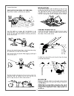
MISCELLANEOUS

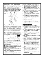
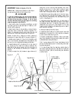
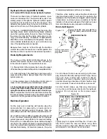
When finishing straight walls or bellholes in sandy soil, use
a platform under the rear tires and the stabilizers. The plat-
form distributes the load over a larger area and lessons the
possibility of a cave-in. The platform also tends to keep the
unit from creeping rearward if hard digging is encountered.

FINISHING STRAIGHT WALLS

Finish the far wall by crowding out while forcing the bucket
down from the boom. Actuate the bucket (curl out) to keep
the bottom of the bucket vertical.

To finish the near wall, lift up and crowd in. Keep the edges
of the bucket horizontal.
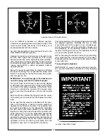
BACKFILLING

Backfill by lifting the bucket over the spoil pile and then
crowding in. Pull both the crowd and lift levers for smooth,
even backfilling.

IMPORTANT: Do not backfill by using the swing circuit
and dragging the bucket sideways. Doing so can cause
damage to the dipperstick boom swing cylinders or
mainframe.

13

Содержание 765H

Страница 1: ...BUSH HOG Operator s Manual MODELS 665H 765H 865H 965H ASSEMBLY OPERATION MAINTENANCE BACKHOES 801 4 00 50034063...

Страница 2: ...ler we stock genuine Bush Hog parts which are manufactured with the same precision and skill as our original equipment Our trained service personnel are well informed on methods required to service Bu...

Страница 3: ...ush Hog dealer from whom he purchased it for service or replacement of defective parts which are covered by warranty Repairs to be sub mitted for warranty consideration must be made within forty five...

Страница 4: ...Bush Hog duty taxes charges for normal service or adjustment loss of crops or any other loss of income rental of substitute equipment expenses due to loss damage detention or delay in the delivery of...

Страница 5: ...he torque chart Machine operates properly Operators manual has been delivered to owner and he has been instructed on the safe and proper use of the backhoe Dealer s Signature CAUTION It is recommended...

Страница 6: ...nd turn the tractor at low speeds 7 Stop tractor engine place transmission in park or neutral engage parking brake lower loader arms to ground cycle all hydraulic controls to relieve pressure allow ma...

Страница 7: ...ck your local government regulations 4 BE SURE the SMV emblem is visible to the rear ADJUSTMENTS AND INSPECTION 1 CHECK pins that attach backhoe to tractor and all pivot pins for tightness several tim...

Страница 8: ...his implement The following decals are located on the backhoe Keep decals clean and replace them immediately if they are missing Contact your dealer or Bush Hog for replacements Location Left Side of...

Страница 9: ...not limited to instructions to Keep all guards in place when the machine is in operation Permit no riders on equipment Stop engine disconnect the power source and wait for all machine movement to stop...

Страница 10: ...stabilizer control levers These controls are located on the control panel directly ahead of the operator See Figure 2 The following is a list of the controls with the function of each reading from lef...

Страница 11: ...ver combined with the two operations performed by the bucket and dip perstick control lever provide four simultaneous oper Operating the Backhoe To avoid possible injury observe the following safety r...

Страница 12: ...the hoe lessens it will begin to move It is balancing the force of one member against the other NOTE Actuating the bucket is the key to powerful dig ging Operating the crowd and bucket controls simul...

Страница 13: ...rs and buck et back up to the full transport height It is normal for the backhoe to slowly settle while being transported Placing the Stabilizers Decreased Digging Depth Narrower Stabilizer Platform S...

Страница 14: ...e crowding it out and swing ing it to the spoil pile As the pile is approached dump the bucket When the bucket is empty the dipperstick and bucket are in position to resume digging upon return to the...

Страница 15: ...finishing straight walls or bellholes in sandy soil use a platform under the rear tires and the stabilizers The plat form distributes the load over a larger area and lessons the possibility of a cave...

Страница 16: ...pped air must be removed after the hoses are connected Start tractor engine and operate backhoe through all movements fully several times to purge the system of air Hydraulic System Hoses Oil leaks in...

Страница 17: ...increases wear greatly After greasing wipe off excessive grease from fittings Figure 6 Lubrication Points for Model 665H Figure 7 Lubrication Points for Model 765H Figure 8 Lubrication Points for Mod...

Страница 18: ...e hydraulic system can now be disconnected CAUTION Make sure tractor PTO is disengaged and engine shut off before disconnecting pump or hydraulic lines a On PTO pump self contained systems the pump sh...

Страница 19: ...t and crowd 8 9 10 11 12 13 23 25 26 E Loss of power in swing cylinders but other cylin ders functioning properly 8 9 10 11 12 13 23 24 26 F Maximum swing action cannot be obtained 12 15 G Slow operat...

Страница 20: ...ow or defective relief pressure will have to be checked and corrections made Backhoe system pressure is 2100 psi for the 665H 2100 psi for the 765H 2400 psi for the 865H and 2250 psi for the 965H Reli...

Страница 21: ...hat they can be reassembled in the same sequence 4 Mount the valve vertically in a vise to facilitate dis assembly and assembly 5 Remove the 3 tie rod nuts from the right end sec tion using a thin wal...

Страница 22: ...ean counterbore 11 Lightly oil new O ring seal Slide O ring seal over valve spool and insert in seal counterbore Replace back up washer seal retainer and seal plate retainer 12 Reattach all parts conn...

Страница 23: ...ackhoe member sup ported by hoist 3 Remove plastic bag containing bucket pins from backhoe Attach Bucket D to Dipperstick using one pin two bolts locknuts pin retainers and washers as needed to take u...

Страница 24: ...4 x 4 1 2 bolt 9 flat washers 10 lock washer 9 and nut 11 Use hoist to raise or lower backhoe slightly until a hole in the upper bar aligns with a hole in the upper braces See Figure 13 6 Attach RH l...

Страница 25: ...ion for further information Pump and reservoir kits are available as options The backhoe is mounted on the tractor lower link arms and an adjustable upper link is supplied to replace the tractor upper...

Страница 26: ...own in Figure 15 Use four carriage 1 2 x 1 3 4 bolts 15 lockwashers 16 and nuts 17 5 Back tractor close to the backhoe Connect tractor lower link arms to lower link mounts at position C Figure 16 usin...

Страница 27: ...actor hydraulic system as described in Hydraulic Hook Up section prior to remounting the backhoe onto the tractor 16 Attach bumper plate 37 to backhoe mainframe using two bolts 38 lockwashers and flat...

Страница 28: ...cted to the pressure port of the trac tor s remote couplers or directly to the tractor valve The return hose B on the backhoe control valve should be connected directly to a port on the reser voir as...

Страница 29: ...r hydraulic reservoir so that it bypasses all other tractor functions Backhoe Operation For the most part a backhoe will function about the same whether it is powered by an open center or closed cente...

Страница 30: ...r link arms and an adjustable upper link is supplied to replace the tractor upper link A set of stabilizer arms are included They bolt from the adjustable upper link to the backhoe mainframe locking t...

Страница 31: ...ces 221 using 3 4 x 5 bolts 203 flat washers 210 and nuts 207 Use hoist to raise or lower backhoe slightly until a hole in the upperr bar aligns with a hole in the upper braces See Figure 21 6 Attach...

Страница 32: ...he reservoir Open center refers to this constant flow through the open center of the valves The assembly instructions cover two conditions that require a power beyond kit to be ordered from Bush Hog T...

Страница 33: ...ation are included in the loader valve kit If the fittings or plugs cannot be located they can be obtained from Bush Hog Service Parts Before attempting to order the plug you must first determine the...

Страница 34: ...erent valves IMPORTANT Never connect the return hose to a tractor remote coupler which can be pressurised Accidental pressurization can cause serious damage to backhoe valve Bush Hog Loader Valve Inle...

Страница 35: ...e are positioned properly and are not pinched or damaged 2 665H and 765H Assemble 90 degree O ring adapter union 2 to power beyond sleeve 1 and direct fitting down through notch in Right Hand foot pad...

Страница 36: ...E LOADER VALVE INLET OUTLET PRESSURE TO BACKHOE VALVE TRACTOR PRESSURE OUT PORT OUTLET INLET RETURN FROM BACKHOE VALVE TEE FITTING RETURN FROM LOADER VALVE TRACTOR RESERVOIR PORT Figure 24 662H 762H B...

Страница 37: ...lock with two nuts 2 10 4 5 GPM PTO PUMP KIT Assemble suction hose 23 to pump 10 using reduc 35 er 14 90 degree beaded fitting 20 and hose clamp 24 as shown in Figure 25 6 1 or 8 GPM PTO PUMP KIT Ass...

Страница 38: ...e 26 6 1 GPM PUMP KIT or 8 GPM PUMP KIT 14 20 15 1 27 9 2 24 10 25 13 7 4 9 2 23 5 21 24 FROM BACKHOE RETURN TO BACKHOE PRESSURE 6 12 3 16 19 18 22 11 17 FILTER ONLY 28 26 18 19 16 3 29 26 12 6 22 11...

Страница 39: ...otation 180 180 180 180 G Loading Reach bucket at 60 3 2 3 7 3 7 4 11 H Transport Overhang 3 5 3 6 4 0 5 1 I Undercut 2 4 2 6 2 10 2 11 J Stabilizer Spread down position 6 6 7 5 8 3 9 3 K Stabilizer S...

Страница 40: ...IZER CYLINDERS BEFORE REMOVING BACKHOE FROM SHIPPING PALLET Cylinder ports must be pointing upward and hoses routed above the cylinder to main frame pivot pin connection Models 865H Shown 965H Models...

Страница 41: ...NOTICE INSTRUCTIONS FOR MOUNTING BUSH HOG BACKHOES ON SKID STEER LOADERS COME WITH THE INDIVIDUAL MOUNTING KITS THE EXAMPLE SHOWN BELOW IS A MODEL 865H MOUNTED ON A JOHN DEERE MACHINE 39...

Страница 42: ...BUSH HOG L L C P O Box 1039 Selma AL 36702 1039 Telephone 334 874 2700 www bushhog com...

Отзывы: