Connection and installation
Product manual 2CKA001473B9085
│16
Device
Note that the connecting cables for the
power supply, the free@home bus and
the external RTC temperature sensor
(option) must be fed through the
previously pierced cable feed-through on
the left side. Also a cable duct (Ø 20 mm)
can be used as an option.
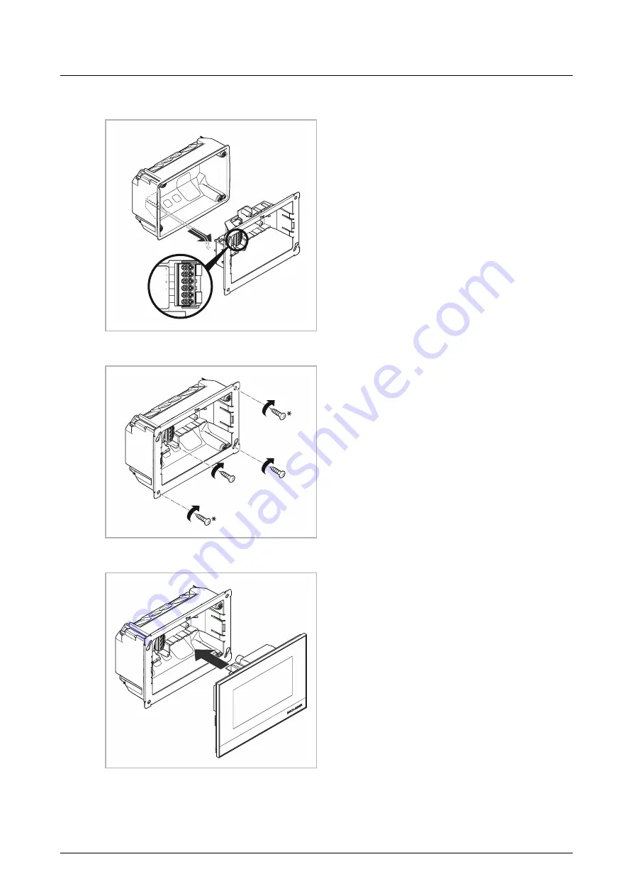
1. Connect the free@home bus line and
power cord of the 24 V power supply
with the terminal block.
– Observe the correct polarity!
– Circuit diagrams: see chapter 5.3
“Circuit diagrams“ on page 14.
Fig. 7:
Connecting wires
2. Insert the support ring into the flush-
mounted installation box.
– A fine adjustment can be carried
out via the two elongated holes.
3. Screw the support ring to the flush-
mounted installation box via the
elongated holes.
– The two other holes *) can be
used for screwing to the wall
(optional!). Here the
corresponding option for fixing to
the wall is to be observed.
Fig. 8:
Mounting the support ring
4. Attach the device to the support ring.
– The device is held magnetically!
Observe the correct position of the multi-
point connector.
Abb. 9:
Attaching the device


