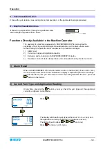
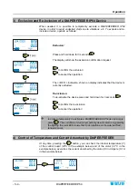
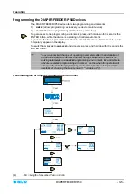
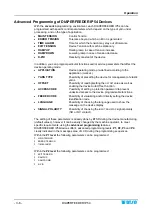
background image

Operation


- 3-2 - 

DIAPERFEEDER IP54


3. + PUSH BUTTON (CONTROL) 

Press this push-button to temporarily de-activate the device

 (lighting of front/rear 

LEDs and of ENTER, RESET, CONTROL push-button LEDs);

 press it again to 

reactivate the device. This button also allows de-activating 

(OFF)

 the power unit. 

During the programming phase, press it to

 increase 

the value of displayed 

parameter. 

  Press this push-button whenever you need to operate on the device 

(i.e. for 

yarn threading, coil separation device adjustment, etc.)

 to avoid undesired 

start-up of the motor. 

+


During normal operation, the three buttons (ENTER, RESET and 
CONTROL) show the green LEDs on.  
In case of alarm, the LEDs turn to red. 


4. LCD DISPLAY 

It provides the real time display of measured and adjusted tension values, as well 
as the parameters programmable within the various menus, programming and error 
messages, device status, etc. 


Symbols shown on LCD 

A – Label Area 

OK 

Indicates the activation of any of the 3 push-buttons of DIAPERFEEDER IP54 device. 

COM 

Communication in progress with SM-DIN/DUOLOOP/** control unit. 

CONTROL 

Indicates that the DIAPERFEEDER IP54 device is operating in Control status. 

PROGRAM 

Indicates that the DIAPERFEEDER IP54 device is in Parameters Programming status. 

P1 

In Control environment indicates that the operating tension is the one defined in P1  

(

MAIN TENSION

).


P2 

In Control environment indicates that the operating tension is the one defined in P2  

(

EXIT TENSION

)

P3 

Not used. 

P4 

It indicates the detection of an optional accessory. 

P5 

Indicates Auto-Offset procedure in progress. 


B – Message Area 

It shows, in the selected language, the various programming menu items, as well as the error messages 
during the device operation, the yarn feeding speed 

(LFA nnnn)

, the device internal temperature, etc. 


Содержание DIAPERFEEDER IP54 DUOLOOP

Страница 1: ...DIAPERFEEDER IP54 DUOLOOP VERSION YARN CONTROL SYSTEM Operating Manual ENGLISH Rev 1 4 February 2016 ...

Страница 2: ... any time the contents of this manual without notice For any technical or commercial problem please contact your local BTSR dealer or call directly BTSR customer service centre We will be glad to meet your needs Thank you for your trust and good job The product described herein is compliant with the requirements of Machine Directive 2006 42 EC and EMC 2004 108 EC All BTSR products are covered by p...

Страница 3: ...d SM DIN DUOLOOP PFN 2 5 Component Identification 2 6 SM DIN DUOLOOP Interface 2 7 Interface SM DIN DUOLOOP ETH SM DIN DUOLOOP PFN 2 9 Configuration of SM DIN DUOLOOP Board 2 11 Configuration of SM DIN DUOLOOP ETH and SM DIN DUOLOOP PFN Boards 2 13 DIAPERFEEDER IP54 overall dimensions in mm 2 13 Instructions for Correct Yarn Threading 2 15 Chapter 3 OPERATION Operating Characteristics of DIAPERFEE...

Страница 4: ...Provided by the Red LEDs on DIAPERFEEDER IP54 Device 4 1 Troubleshooting Table 4 2 Errors detected on the SM DIN DUOLOOP boards 4 5 Errors detected on the Board SM DIN DUOLOOP ETH and SM DIN DUOLOOP PFN 4 6 Calibration of Tension sensors 4 8 Coil separator adjustment 4 9 Periodic cleaning of the components 4 10 ...

Страница 5: ...SR systems Thanks to its modularity characteristics the DIAPERFEEDER IP54 device is capable of managing not only the TS44 tension sensor but also the IS3F image scanning sensor thus allowing the user to obtain a complete quality control for what concerns both the yarn tension and the correct yarn running condition DUOLOOP solution for automatic diaper production lines Since for space reason it is ...

Страница 6: ...Introduction I 2 DIAPERFEEDER IP54 DUOLOOP solution Summary diagram SERIAL LINE SERIAL LINE ELASTIC YARNS PRODUCTION LINE PROFIBUS SERIAL LINE SERIAL LINE ELASTIC YARNS PRODUCTION LINE PROFIBUS ...

Страница 7: ...hich the attention of the reader should be directed Indicates a particularly sensitive situation which could have an effect on the safety or proper operation of the system TENSION ERROR All the items concerning the device programming menus within this manual are always show in CAPITAL LETTERS TS44 TS55 IS3F To make the description easier the interface Boards SM DIN DUOLOOP SM DIN DUOLOOP ETH SM DI...

Страница 8: ...Introduction I 4 DIAPERFEEDER IP54 Page intentionally left blank ...

Страница 9: ... in graphical form both the average and peak values of the yarn tension The DIAPERFEEDER IP54 devices are controlled by two DSPs Digital Signal Processor and by ASIC components BTSR Patent which provide great versatility parameters may be programmed depending on the various yarn processing conditions The Full Digital Technology also allows performing a number of extremely accurate controls on the ...

Страница 10: ...rocess Advantages obtained by using the SMART MATRIX WINDINGFEEDER Terminal combined with DIAPERFEEDER IP54 Devices Using the SMART MATRIX BTSR terminal connected to DIAPERFEEDER IP54 devices you have the possibility of developing a wide range of functions which facilitate the practical use of the installed DIAPERFEEDER IP54s immediate download and upload of data as well as displaying fundamental ...

Страница 11: ...ee IP54 IS3F Power supply voltage 12 24 Vdc 20 Absorption 15 mA max 20 mA STOP output NPN STOP output protection Protection against over voltages short circuits Maximum Current of STOP output 200 mA continuous 500 mA peack Reaction Delay Programmable from 5 to 1 000 msec Sensitivity Programmable 10 levels Signaling With integrated LEDs Dimensions mm 15x15x36 5 Narrow 25x15x36 5 Wide Operating temp...

Страница 12: ...PERFEEDER IP54 Electrical Interface of DIAPERFEEDER IP54 Devices TS44 Connector for TS44 1000RW IP tension sensor connection POWER Connector power connection IS3 Connector for IS3F yarn image sensor connection IS3F TS44 POWER TS44 POWER IS3F ...

Страница 13: ...ollowing figure shows an application example comprising 4 DIAPERFEEDER IP 54 devices 1 SM DIN DUOLOOP board 1 PSU 10AS switching power supply and 4 TS55 tension control sensors Concerning all electrical systems it is a suggested rule to ensure that the ground cable GND is connected to the device support ...

Страница 14: ...Technical Data and Installation 2 4 DIAPERFEEDER IP54 Example of application 4 positions Ethernet IP network Board SM DIN DUOLOOP ETH ...

Страница 15: ...Technical Data and Installation DIAPERFEEDER IP54 2 5 Example of application 4 positions Profinet network Board SM DIN DUOLOOP PFN ...

Страница 16: ...g IFE 400 IMA 001 400 cm power chord machine interface IP67 CN X8 002 M5M12 Socket with connection cable and 5 poles connectors IP67 M12 CNS 003 Socket outlet protection cap FE30 VSL Profibus adapter cable SMDIN DUOLOOP System management board profibus converter SMDIN DUOLOOP ETH System management board profibus converter SMDIN DUOLOOP PFN System management board profibus converter SMPRFB 2000 IP ...

Страница 17: ...FEEDER IP54 2 7 SM DIN DUOLOOP Interface Machine Interface INPUT Machine Interface OUTPUT DIAPERFEEDER IP54 chain DIAPERFEEDER IP54 chain TS55 chain TS55 chain Max 10 DIAPERFEEDER IP54 devices and 10 TS55 sensors PROFIBUS Interface PSU 20AS ...

Страница 18: ...pply voltage 24 VDC Maximum absorption 200 mA Max Protection fuse Board protection 5 A Protection fuse sensors supply 3 A 0 3 A 125 VAC STOP output normally open contacts 1 A 30 VDC 0 24 VDC VIL Max 1 2 VDC Inputs VIH Min 5 VDC Operating temperature range 10 60 C Storage temperature 25 85 C Dimensions 138 5x124x35 mm ...

Страница 19: ...DER IP54 2 9 Interface SM DIN DUOLOOP ETH SM DIN DUOLOOP PFN Machine Interface INPUT Machine Interface OUTPUT DIAPER FEEDER Chain TS55 Chain Max 10 DIAPER FEEDER devices and 10 TS55 sensors PROFIBUS Interface PSU 20AS option ETHERNET interface ...

Страница 20: ...VAC 24 VDC Maximum absorption 200 mA Max Protection fuse Board protection 3 A Protection fuse sensors supply 3 A 0 3 A 125 VAC STOP output normally open contacts 1 A 30 VDC 0 24 VDC VIL Max 1 2 VDC Inputs VIH Min 5 VDC Operating temperature range 10 60 C Storage temperature 25 85 C Dimensions 138 5x124x35 mm ...

Страница 21: ...e when the machine is stopped P05 Tension control on TS55 sensors P06 Offset on TS55 sensors Procedure Run Time status During the normal machine operation Parameter Edit status Parameter P01 Board identification number To increase the value To decrease the value for this application always set 001 Parameter P02 Baudrate Always set 115 Kbps Parameter P03 regulation algorithm system gain setting Pos...

Страница 22: ...m SM DIN DUOLOOP see note 2 End of programming sequence and return to Run Time status Run Time status Note 1 When selecting AuT the system automatically sets the value of tension to keep on the yarn with machine stationary depending on the value self learnt during the transition from machine running status to machine stopped status start stop signal switching Note 2 To carry out the offset operati...

Страница 23: ...ERFEEDER IP54 2 13 Configuration of SM DIN DUOLOOP ETH and SM DIN DUOLOOP PFN Boards For the configuration of SM DIN DUOLOOP ETH and SM DIN DUOLOOP PFN Boards please refer to the relevant manual DIAPERFEEDER IP54 overall dimensions in mm ...

Страница 24: ...ce fastening screws No 2 TS44 1000rw Tension Sensor A Fastening hole with M4 x 20 screw B Loading cell tension sensor Note the TS44 device may automatically carry out the offset function upon special command issued by DIAPERFEEDER IP54 device see OFFSET AUTO parameter on P3 programming level A B TS44 1000RW IP A B CABLE LENGTH 50cm POWER CONNECTOR ...

Страница 25: ...round the roller passing beneath the separation element as shown on the figure above Set the yarn over the loading cell of TS44 sensor and thread it out of the upper buckle For correct separation of yarn coils on the coil separation element slightly tilt the separation device while the DIAPERFEEDER IP54 is running turning the adjustment screw E F B C D A ...

Страница 26: ...Technical Data and Installation 2 16 DIAPERFEEDER IP54 Page intentionally left blank ...

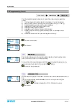
Страница 27: ...uring the programming phase press it to confirm the displayed parameter Pressing and holding down this push button for about 3 seconds on particular parameters you will have the possibility to enable disable the corresponding function 2 PUSH BUTTON RESET Press this push button to cancel possible error signaling on DIAPERFEEDER IP54 display red LED flashing During the Programming phase press it to ...

Страница 28: ...eters programmable within the various menus programming and error messages device status etc Symbols shown on LCD A Label Area OK Indicates the activation of any of the 3 push buttons of DIAPERFEEDER IP54 device COM Communication in progress with SM DIN DUOLOOP control unit CONTROL Indicates that the DIAPERFEEDER IP54 device is operating in Control status PROGRAM Indicates that the DIAPERFEEDER IP...

Страница 29: ...ation reading 3 Exclusion and re inclusion of a DIAPERFEEDER IP54 device 4 Real time control of device temperature and current absorbed by the device motor 1 Alarm Reset When a DIAPERFEEDER IP54 device detects an Error condition E2 Tension Error etc the device stops and the LFA nnnn indication on display is replaced by the error message To reset the alarm once you have removed the cause that gener...

Страница 30: ...vice is currently excluded Re inclusion To re activate the device press and hold down for 3 seconds to confirm the re inclusion to cancel the operation In order to temporarily de activate a DIAPERFEEDER IP54 device simply press The condition of device temporarily de activated is signaled by the lighting the red LEDS inside the 3 push buttons and inside theTS44 tension sensor 4 Control of Temperatu...

Страница 31: ... Firmware version will temporarily appear on the display To switch from SIMPLE to ADVANCED and viceversa press and hold down for 3 seconds the ENTER button To avoid undesired changes of operating parameters after the installation of DIAPERFEEDER IP54 devices and after having setup and checked all the working parameters in ADVANCED programming environment it is advisable to activate the SIMPLE prog...

Страница 32: ...ns OFFSET Possibility of reading setting the OFFSET value as well as enabling the device Auto Offset function ACCESS CODE Possibility of setting a protection password to prevent undesired access to the device programmable functions FEEDER CODE Possibility of visualizing and or directly setting the device identification code LANGUAGE Possibility of choosing the language used to show the message on ...

Страница 33: ...N TYPE ALL YARN OR ELASTIC LANGUAGE SELECTION USE OF INTELLIGENT TENSION CONTROL ACCESSORY Press the Control button to switch from one programming level to the next one Press Reset button to quit the programming environment The following pages provide detailed information about the DIAPERFEEDER IP54 device programming However in the SMART MATRIX WINDINGFEEDER application the parameter programming ...

Страница 34: ...ram of P1 P4 Advanced Programming Levels and Default Settings NOTES The values shown refer to the default parameters set by BTSR A LFA Length of Absorbed Yarn in m min B The selectable languages are Italian English French Spanish German Japanese ...

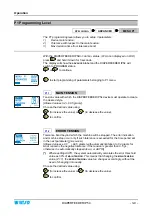
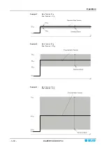
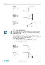
Страница 35: ...ues 0 2 99 5 grams Choose the desired value using to increase the value or to decrease the value to confirm P1 2 ERROR TENSION Tolerance band beyond which the machine will be stopped The error indication and machine stop occur only if such tolerance is exceeded for the time period set in the next parameter TIME ALARM Allowed values 0 0 99 5 grams with automatic limitation to 0 4 grams for what con...

Страница 36: ...Operation 3 10 DIAPERFEEDER IP54 Example 1 Main Tension 20 g Error Tension 5 g Example 2 Main Tension 50 g Error Tension 20 g Example 3 Main Tension 5 0 g Error Tension 6 g ...

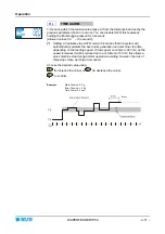
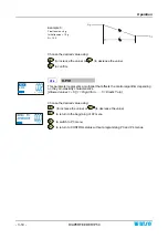
Страница 37: ...this means that the system will automatically calculate the best alarm generation and machine stop time depending on the feeding speed At low speed such time is 500 ms as the speed increases it will be reduced up to a minimum of 50 ms this allows a quick machine stop during normal operation avoiding however the risk of false stops when working at low speed Choose the desired value using to increas...

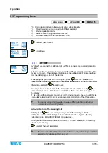
Страница 38: ...le the function press and hold down for 3 seconds the Enter button The OFF indication means that the function has been disabled In this case the EXIT TENSION parameter will assume the same value set on MAIN TENSION parameter within the P1 programming level To re enable this function press and hold down for 3 seconds the Enter button The OFF indication will disappear and it will be replaced by a mo...

Страница 39: ...ion in such a way as to avoid excessive yarn relaxations Allowed values 1 250 The RAMP DOWN t is calculated using a reference table that determines an increase of the ramp time depending on the programmed value 1 very fast ramp time 1ms 250 very slow ramp time 250 msec See the following examples where N value programmed with parameter P2 3 Ramp Down T1 final tension value low T2 initial tension va...

Страница 40: ...2 4 K PID This parameter represents a multiplier that affects the control algorithm depending on the yarn elasticity characteristics Allowed values 1 5 1 Rigid Yarn 5 Elastic Yarn Choose the desired value using to increase the value or to decrease the value to return to the beginning of P2 menu to switch to P3 menu to return to CONTROL status without programming P3 and P4 menus ...

Страница 41: ...SET value If the two values are different press briefly to align them You may either enable or disable the Automatic Offset function keeping pressed for 3 seconds If the function is disabled then AUTO does not appear on the display If it is enabled then at every machine stop the device loosens the yarn until this is completely relaxed and it carries out an automatic correction of the Offset value ...

Страница 42: ...ly disabled If you specify an access code this will be requested each time you attempt to activate the programming environment When the CODE request appears type the secret key code using and buttons increase the value of secret key code decreases the value of secret key code Press to save the key code and move to the next parameter P3 4 FEEDER CODE This function allows you to visualize and or set...

Страница 43: ...of Input and Stop signals Normally Open or Normally Closed contact 8 Automatic detection of the optional intelligent accessory to select the P4 level to continue P4 1 MOTOR D This function allows you to choose the rotation direction of yarn feeding motor CW Clockwise CCW Counter Clockwise To move from CW value Clockwise to CCW value Counter Clockwise or vice versa press and hold down for 3 seconds...

Страница 44: ...oose between ELASTIC or ALL YARN options to confirm the application shown on display and move to the next parameter The ELASTIC mode allows a better handling of bare elastic yarns P4 6 LANGUAGE SELECTION This function allows you to select the language used to display menu items messages and errors or to scroll forward backward the list of available languages ITALIANO ENGLISH FRANCAIS ESPANOL DEUTS...

Страница 45: ... and OFF to confirm and return to P4 menu to return to CONTROL status Management of Tension Error Alarm EXAMPLE The DIAPERFEEDER IP54 generates the Error Tension Alarm when the tension goes out of the programmed tolerance band and automatically resets the alarm as soon as the tension returns within the programmed tolerance band Error Tension Alarm active only when the DIAPERFEEDER IP54 device oper...

Страница 46: ...Operation 3 20 DIAPERFEEDER IP54 Page intentionally left blank ...

Страница 47: ... GREEN RED ALTERNATE FLASHING MOTOR LOCKED with CONTROL button ON ON TENSION ERROR BLINKING GREEN RED ALTERNATE FLASHING This condition is obtained when you are working with the tension defined in P2 If you are working with the tension defined in P1 even if you press the Control button the LEDs remain off However pressing the Control button the tension defined in P1 will be displayed To interpret ...

Страница 48: ...on DIAPERFEEDER IP54 device as indicated on P3 level ES ES CONT displayed on DIAPERFEEDER IP54 display 1 Internal protection against overcurrents 1 Reset the alarm if the problem persists contact your BTSR reseller MT BUS displayed on DIAPERFEEDER IP54 display 1 Supply voltage lower than 15 Vdc 1 Check the supply voltage if the problem persists contact your BTSR reseller CURRENT displayed on DIAPE...

Страница 49: ...e SMART MATRIX WINDINGFEEDER terminal or set directly the identification code on DIAPERFEEDER IP54device parameter P3 4 2 Check the correct operation of SMART MATRIX WINDINGFEEDER terminal using the numbering procedure described in the SMART MATRIX WINDINGFEEDER manual 3 Check the overall device wiring ASC1010 COM ERROR displayed on DIAPERFEEDER IP54 display 1 Missing communication between main DS...

Страница 50: ...your local BTSR reseller giving a detailed description of the kind of fault and the conditions in which it occurred Should be necessary to call the BTSR Technical Service Department read the code printed on the faulty device as this information could be useful to BTSR technicians Example Device code DIAPERFEEDER IP54 ...

Страница 51: ...e maximum threshold on a DIAPERFEEDER device Spool runout signaling Signaling for exhaustion of one of the two spools relevant to a DIAPERFEEDER device Device type error a device different from a DIAPERFEEDER device has been connected to the system Broken yarn alarm on a DIAPERFEEDER device The machine is operating but the yarn feeding is not detected Uncut yarn alarm on a DIAPERFEEDER device A ya...

Страница 52: ...e Diaper Feeder device locked the button on the device has been pressed Door open Spool holder carriage not correctly inserted Left spool exhausted Matrix Cube 2 Right spool exhausted Matrix Cube 2 One spool exhausted Matrix Cube Diaper Feeder device upgrade in progress with PC directly connected to Smart Matrix terminal Error due to tension too low on a Diaper Feeder device ...

Страница 53: ...age appears when the identification is executed from PC or Smart Matrix terminal HTP Matrix Cube sensor identification in progress This message appears when the identification is executed from PC or Smart Matrix terminal HTP Matrix Cube 2 sensor identification in progress This message appears when the identification is executed from PC or Smart Matrix terminal The position of the involved sensor d...

Страница 54: ...ration procedure please refer to Configuration of SM_DIN DUOLOOP Board paragraph Note 2 We remind you that prior to confirm the execution of OFFSET function you must remove the yarn from the loading cell of the involved sensors Should the calibration procedure OFFSET not be correctly executed Tension read after the calibration without yarn not close to 0 try to touch the loading cell with a finger...

Страница 55: ...ator safety it s always advisable to lock the motor prior to operate on the devices yarn threading tilt adjustment of coil separation element etc in order to avoid unexpected motor startup events To lock the motor just press the button on the DIAPERFEEDER IP54 device and check the lighting of buttons red LEDs and of TS44 sensor At the end of the operation press again the button and make sure that ...

Страница 56: ...at an excessive accumulation of dirtiness especially when combined with a high ambient humidity may lead to a deterioration of the system general performance and reliability To clean the system components you may use an industrial vacuum cleaner and or a compressed air blow keeping the gun at a distance not lower than 20 cm from the item to be cleaned and adjusting the air pressure to a value 4bar...

Страница 57: ...BTSR International S p A Via S Rita 21057 OLGIATE OLONA VA Phone 0331 323202 Fax 0331 323282 Internet www btsr com REV 1 4 02 16 DISTRIBUTOR ...

Отзывы: