


577C--C, 577C--E, 577C--F: Installation Instructions
Manufacturer reserves the right to change, at any time, specifications and designs without notice and without obligations.
49
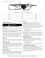
For models that have a scroll compressor, the compressor pumps
refrigerant throughout the system by the interaction of a stationary and
an orbiting scroll. The scroll compressor has no dynamic suction or
discharge valves, and it is more tolerant of stresses caused by debris,
liquid slugging, and flooded starts. The compressor is equipped with a
noise reducing shutdown device and an internal pressure relief port. The
pressure relief port is a safety device, designed to protect against
extreme high pressure. The relief port has an operating range between
550 (26.34 kPa) and 625 psig (29.93 kPa) differential pressure.
Refrigerant System
This information covers the refrigerant system including the compressor
oil needed, servicing systems on roofs containing synthetic materials, the
filter drier and refrigerant charging.
Compressor Oil
The Copeland scroll compressor uses 3MAF POE oil. If additional oil is
needed, use Uniqema RL32-3MAF. If this oil is not available, use
Copeland Ultra 32 CC or Mobil Arctic EAL22 CC. This oil is extremely
hygroscopic, meaning it absorbs water readily. POE oils can absorb 15
times as much water as other oils designed for HCFC and CFC
refrigerants. Take all necessary precautions to avoid exposure of the oil
to the atmosphere.
Rotary Compressor
The 24 and 30 size units use a single cylinder rotary compressor. This
compressor utilizes a rotor which is positioned eccentrically with respect
to the shell. Refrigerant gas is ported directly into the compression
chamber and discharged into the surrounding area. It is also known as a
“high-side” design since high pressure gas surrounds the motor and
compression chamber. The majority of the shell will be hot to the touch.
The rotary compressor also utilizes an external built-in accumulator to
reduce the likelihood of refrigerant liquid from entering the compressor.
Servicing Systems on Roofs with Synthetic
Materials
POE (polyolester) compressor lubricants are known to cause long term
damage to some synthetic roofing materials.
Exposure, even if immediately cleaned up, may cause embrittlement
(leading to cracking) to occur in one year or more. When performing any
service that may risk exposure of compressor oil to the roof, take
appropriate precautions to protect roofing. Procedures which risk oil
leakage include, but are not limited to, compressor replacement,
repairing refrigerant leaks, replacing refrigerant components such as
filter drier, pressure switch, metering device, coil, accumulator, or
reversing valve.
Synthetic Roof Precautionary Procedure
1. Cover extended roof working area with an impermeable
polyethylene (plastic) drip cloth or tarp. Cover an approximate 10
X 10 ft. (3.1 m X 3.1 m) area.
2. Cover area in front of the unit service panel with a terry cloth shop
towel to absorb lubricant spills and prevent run-offs, and protect
drop cloth from tears caused by tools or components.
3. Place terry cloth shop towel inside unit immediately under
component(s) to be serviced and prevent lubricant run-offs through
the louvered openings in the unit base.
4. Perform required service.
5. Remove and dispose of any oil contaminated material per local
codes.
Liquid Line Filter Drier
This filter drier is specifically designed to operate with Puron (R-410A).
Use only factory-authorized components. Filter drier must be replaced
whenever the refrigerant system is opened. When removing a filter drier,
use a tubing cutter to cut the drier from the system. Do not unsweat a
filter drier from the system. Heat from unsweating will release moisture
and contaminants from drier into system.
Puron (R-410A) Refrigerant Charging
Refer to unit information plate and charging chart. Some R-410A
refrigerant cylinders contain a dip tube to allow liquid refrigerant to flow
from cylinder in upright position. For cylinders equipped with a dip tube,
charge Puron (R-410A) units with cylinder in upright position and a
commercial metering device in manifold hose. Charge refrigerant into
suction-line.
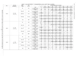
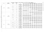
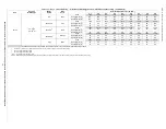
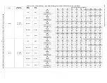
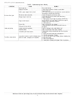
Troubleshooting
Use the Troubleshooting Guides (See
, and
if problems occur with these units.
Start-up Checklist
Use Start-Up checklist to ensure proper start-up procedures are followed.
My Learning Center is your central location for professional residential
HVAC training resources that help strenghten careers and businesses.
We believe in providing high quality learning experiences both online
and in the classroom.
Access My Learning Center with your HVACpartners credentials at
with questions.
WARNING
!
FIRE/EXPLOSION HAZARD
Failure to follow this warning could result in personal injury or death
and/or property damage.
Wear safety glasses and gloves when handling refrigerants. Keep
torches and other ignition sources away from refrigerants and oils.
WARNING
!
EXPLOSION, ENVIRONMENTAL SAFETY HAZARD
Failure to follow this warning could result in personal injury, death or
equipment damage.
This system uses Puron (R-410A) refrigerant which has higher
operating pressures than R-22 and other refrigerants. No other
refrigerant may be used in this system. Gauge set, hoses, and recovery
system must be designed to handle Puron (R-410A). If you are unsure,
consult the equipment manufacturer.


