Bryant GB1AAV Скачать руководство пользователя страница 6

e. Gas valve

f. Hot surface ignitor

g. Flame-sensing electrode

6. Remove 8 screws that secure flue collector box to center panel. Be careful not to damage sealant.

7. Remove complete inducer assembly from furnace, exposing flue openings.

8. Clean cells using field-provided small wire brush, steel spring cable, reversible electric drill, and vacuum cleaner.

a. Assemble wire brush and steel spring cable.

(1.) Use 48 in. of 1/4-in. diameter high-grade steel spring cable (commonly known as drain clean-out or Roto-Rooter cable).

(2.) Use 1/4-in. diameter wire brush (commonly known as 25-caliber rifle cleaning brush).

NOTE:

The materials needed in items (1.) and (2.) can usually be purchased at local hardware stores.

(3.) Insert twisted wire end of brush into end of steel spring cable, and crimp tight with crimping tool or strike with ball-peen hammer.

TIGHTNESS is very important.

(4.) Remove metal screw fitting from wire brush to allow insertion into cable.

b. Clean each heat exchanger cell.

(1.) Attach variable-speed, reversible drill to end of steel spring cable (end opposite brush).

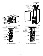
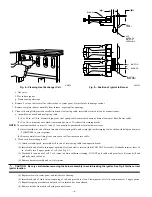
(2.) Insert brush end of cable into upper opening of cell and slowly rotate with drill. DO NOT force cable. Gradually insert at least 36

in. of cable into 2 upper passes of cell. (See Fig. 8.)

(3.) Work cable in and out of cell 3 or 4 times to obtain sufficient cleaning. DO NOT pull cable with great force. Reverse drill and

gradually work cable out.

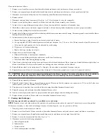
(4.) Remove burner assembly and cell inlet plates.

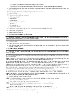
CAUTION: Be very careful when removing the burner assembly to avoid breaking the ignitor. See Fig. 9 for the correct

ignitor location.

(5.) Replace screws in center panel and cells before cleaning.

(6.) Insert brush end of cable in lower opening of cell, and proceed to clean 2 lower passes of cell in same manner as 2 upper passes.

(7.) Repeat foregoing procedures until each cell in furnace has been cleaned.

(8.) Remove residue from each cell using vacuum cleaner.

Fig. 8—Cleaning Heat Exchanger Cell

A91252

Fig. 9—Position of Ignitor to Burner

A93347

BURNER

IGNITOR

11 32

"

7 8

"

C

L

C

L

IGNITOR
ASSEMBLY

CELL
PANEL

BURNER

13 32

"

HOT
SURFACE
IGNITOR
ASSEMBLY

—6—

Содержание GB1AAV

Страница 1: ...en working on heating equipment observe precautions in the literature on tags and on labels attached to or shipped with the unit and other safety precautions that may apply Follow all safety codes In...

Страница 2: ...ouch ungrounded objects recharge your body with static electricity firmly touch furnace again before touching control or wires 5 Use this procedure for installed and uninstalled ungrounded furnaces 6...

Страница 3: ...th sides of the furnace d Slide filter s out e Replace filter if torn or disposable type If furnace is equipped with permanent washable filters Clean filters with tap water Spray water through filter...

Страница 4: ...6 Model GB1AAV Upflow A92063 C OM 24V HUM G R Y W DRAFT SAFEGUARD SWITCH FLUE COLLECTOR BOX MOUNTING SCREWS RELIEF BOX CONTROL BOARD FILTER RETAINER WASHABLE FILTER Fig 7 Model GB3AAV Downflow A92064...

Страница 5: ...on blower wheel blades The blower wheel should not be dropped or bent as balance will be affected 14 Reinstall blower wheel by reversing items 12 a through c Be sure wheel is positioned for proper rot...

Страница 6: ...h heat exchanger cell 1 Attach variable speed reversible drill to end of steel spring cable end opposite brush 2 Insert brush end of cable into upper opening of cell and slowly rotate with drill DO NO...

Страница 7: ...d for proper operation of the control board and flame sensing electrode The 24 v circuit contains an automotive type 3 amp fuse located on the control board See Fig 11 Any direct shorts of the 24 v wi...

Страница 8: ...on thermostat connection block See Fig 11 NOTE If TEST to Com terminals are jumpered longer than 2 sec LED will flash rapidly and retrieval request will be ignored e Component Test will function as de...

Страница 9: ...IGHT HARNESS CONNECTOR 24 V TRANSFORMER SEC 2 SPARE 1 SPARE 2 EAC 1 EAC ELECTRONIC AIR CLEANER TERMINALS 115 VAC 1 5 AMP MAX EAC 2 115 VAC L2 NEUTRAL CONNECTION 24 V THERMOSTAT TERMINALS BLOWER SPEED...

Страница 10: ...MPONENT TEST TWIN TERMINAL TRAN TRANSFORMER 115VAC 24VAC JUNCTION UNMARKED TERMINAL PCB TERMINAL FACTORY WIRING 115VAC FACTORY WIRING 24VAC FIELD WIRING 115VAC FIELD WIRING 24VAC CONDUCTOR ON PCB FIEL...

Страница 11: ...lay 33 LIMIT OR FLAME ROLL OUT SWITCH IS OPEN If open longer than three minutes code changes to 13 Check for Defective blower motor or start capacitor Dirty filter or restricted duct system Loose blow...

Страница 12: ...tatus code The status code is a 2 digit number with the first digit determined by the number of short flashes and the second digit by the number of long flashes Once status code is determined the cont...

Страница 13: ...ault is cleared Check for Stuck open gas valve solenoid or leak Defective control board 23 PRESSURE SWITCH WILL NOT OPEN Check for Disconnected or obstructed pressure tubing Defective pressure switch...

Страница 14: ...t theory and skills programs is available using popular video based formats and materials All include video and or slides plus companion book Classroom Service Training plus hands on the products in o...

Страница 15: ...15...

Страница 16: ...1996 CAC BDP P O Box 70 Indianapolis IN 46206 sggb1a09 16 Book Tab 1 6a 4 8a Catalog No 92 33GB 1A23...

Отзывы: