background image

57

Adjustments

FIRE HAZARD

Failure to follow this warning could result in personal

injury, death and/or property damage.
DO NOT bottom out gas valve regulator adjusting screw.

This can result in unregulated manifold pressure and result

in excess overfire and heat exchanger failures.

!

WARNING

FURNACE DAMAGE HAZARD

Failure to follow this caution may result in reduced furnace

life.
The 26,000 BTUH model has a lower nominal manifold

pressure than other models. Do not adjust the natural gas

manifold pressure above 1.8--in. W.C.
The 26,000 BTUH model can be identified by the green

label affixed to the solenoid of the gas valve.
Refer to the Adjustment section for setting the manifold

pressure.
USE TABLE 19 WHEN ADJUSTING 26,000 BTUH

MODEL MANIFOLD PRESSURE.

CAUTION

!

FURNACE DAMAGE HAZARD

Failure to follow this caution may result in reduced furnace

life.

DO NOT redrill orifices. Improper drilling (burrs,

out--of--round holes, etc.) can cause excessive burner noise and

misdirection of burner flames. This can result in flame

impingement of heat exchangers, causing failures. See Fig.

59.

CAUTION

!

For proper operation and long term reliability, the Furnace input

rate must be /--2 percent of input rate on furnace rating

plate, or as adjusted for altitude.
The gas input rate on rating plate is for installations at altitudes up

to 2000 ft. (609.6M).

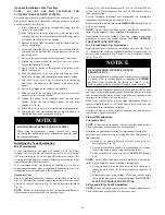
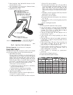
BURNER 

ORIFICE

A93059

Fig. 59 -- Orifice Hole

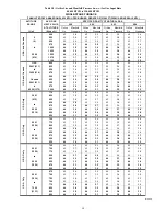
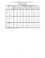
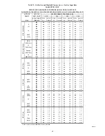
The NATURAL GAS manifold pressure adjustments in Tables

18 and 19 compensate for BOTH altitude AND gas heating

value. DO NOT apply an additional de--rate factor to the

pressures show in Table 18 and 19. The values in this table

are NOT referenced to sea level; they are AS--MEASURED

AT ALTITUDE.
The heating content of natural gas at altitude may already

provide for a reduction in capacity of the furnace. Be sure to

obtain the expected in--season gas heating value of the gas

from the gas supplier BEFORE making any adjustments for

capacity or altitude.

Refer to Table 18 and 19.

No

adjustments to the furnace may be necessary at altitude for

certain gas heating values.
Refer to the instructions provided in the factory--specified

LP/Propane conversion kit for instructions for setting gas

manifold pressures for LP/Propane applications.

NOTICE

In the USA., the input rating for altitudes above 2000 ft. (609.6M)

must be reduced by 2 percent for each 1000 ft. (304.8M) above sea

level. Refer to Table 18 or 19 . The natural gas manifold pressures

in Table 19 adjust for BOTH altitude and natural gas heating value.
In Canada, the input rating must be reduced by 5 percent for

altitudes of 2000 ft. (609.6M) to 4500 ft. (1371.6M) above sea

level. The natural gas manifold pressures in Table 18 adjust for

BOTH altitude and natural gas heating value.

NOTE

: For Canadian altitudes of 2000 to 4500 ft. (610 to 1372

M), use USA altitudes of 2001 to 2000 ft. (611 to 914 M) in Table

18 or 19.
To adjust manifold pressure to obtain the proper input rate, first,

determine if the furnace has the correct orifice installed. At higher

altitudes or different gas heat contents, it may be necessary to

change the factory orifice to a different orifice. Tables have been

provided in the furnace installation instructions to match the

required orifice to the manifold pressure to the heat content and

specific gravity of the gas. To do this:

1. Obtain average yearly gas heat value (at installed altitude)

from local gas supplier.

2. Obtain average yearly gas specific gravity from local gas

supplier.

3. Find installation altitude in Table 18 or 19.
4. Find closest natural gas heat value and specific gravity in

Table 18 or 19. Follow heat value and specific gravity lines

to point of intersection to find orifice size and manifold

pressure settings for proper operation.

5. Check and verify burner orifice size in furnace. NEVER

ASSUME ORIFICE SIZE. ALWAYS CHECK AND

VERIFY.

If orifice hole appears damaged or it is suspected to have been

redrilled, check orifice hole with a numbered drill bit of

correct size. Never redrill an orifice. A burr--free and squarely

aligned orifice hole is essential for proper flame characteristics.

NOTICE

6. Replace orifice with correct size, if required by Table 18 or

19. Use only factory--supplied orifices. See EXAMPLE 1.

EXAMPLE

1: 0 -- 2000 ft. (0 -- 609.6M) altitude

Heating value = 1050 Btu/cu ft.
Specific gravity = 0.62
Therefore: Orifice No. 44
Manifold pressure: 3.4--in. w.c. (847 Pa)
(Furnace is shipped with No. 44 orifices. In this example, all main

burner orifices are the correct size and do not need to be changed to

obtain proper input rate.)

NOTE

: To convert gas manifold Table pressures to Pascals,

multiply the in. w.c. value by 249.1 Pa/in. w.c. (1 in. w.c. = 249.1

Pa).

Содержание 915SB

Страница 1: ...Opening Dimensions 25 Air Delivery CFM 26 Maximum Capacity of Pipe 28 Electrical Data 33 Vent Termination Kit for Direct Vent 2 Pipe System 36 Hangar Spacing 42 Combustion Air Vent Pipe Fitting Cement...

Страница 2: ...exhaust vent terminal for the horizontally vented gas fueled heating appliance or equipment The sign shall read in print size no less than one half 1 2 inch in size GAS VENT DIRECTLY BELOW KEEP CLEAR...

Страница 3: ...king on heating equipment observe precautions in literature on tags and on labels attached to or shipped with furnace and other safety precautions that may apply These instructions cover minimum requi...

Страница 4: ...n be converted in the field for use with propane gas when a factory supplied conversion kit is used Refer to the furnace rating plate for conversion kit information These furnaces are not approved for...

Страница 5: ...ensed plumber or gas fitter S When flexible connectors are used the maximum length shall not exceed 36 in 914 mm S When lever type gas shutoffs are used they shall be T handle type S The use of copper...

Страница 6: ...8 3 4 222 126 5 57 4 36060E14 14 3 16 361 12 1 2 319 12 9 16 322 7 1 8 181 129 58 5 42060E17 17 1 2 445 15 7 8 403 16 406 8 3 4 222 138 5 62 8 48080E17 17 1 2 445 15 7 8 403 16 406 8 3 4 222 146 5 66...

Страница 7: ...parts bag contents This furnace must S be installed so the electrical components are protected from water S not be installed directly on any combustible material other than wood flooring refer to SAF...

Страница 8: ...must be installed in accordance with the current edition of NFPA 54 ANSI Z223 1 or CAN CSA B149 2 See Fig 4 WARNING 18 IN 457 2 mm MINIMUM TO BURNERS A93044 Fig 4 Installation in a Garage FIRE HAZARD...

Страница 9: ...e Air contaminants are found in aerosol sprays detergents bleaches cleaning solvents salts air fresheners and other household products CAUTION CARBON MONOXIDE POISONING HAZARD Failure to follow this w...

Страница 10: ...2 kW of the total input rating of all gas appliances in the space but not less than 100 in 2 0 06 m2 One opening shall commence within 12 in 300 mm of the ceiling and the second opening shall commence...

Страница 11: ...ce Volumes for 100 Combustion Ventilation and Dilution Air from Outdoors AIR CHANGES PER HOUR ACH OTHER THAN FAN ASSISTED TOTAL 1 000 S BTUH GAS INPUT RATE FAN ASSISTED TOTAL 1 000 S BTUH GAS INPUT RA...

Страница 12: ...required for all direct vent horizontal installations only The kit contains a rubber casing grommet designed to seal between the furnace casing and the condensate trap See Fig 8 Remove knockout Insta...

Страница 13: ...operation or damage to equipment If furnace environment has the potential of freezing the drain trap and drain line must be protected The use of accessory drain trap heaters electric heat tape and or...

Страница 14: ...d two spring clamps from the loose parts bag 3 Slide a spring clamp 1 inch 25 mm down the plain end the end without the formed grommet of the drain elbow 4 From inside the casing insert the formed gro...

Страница 15: ...zontal drain trap grommet is ONLY REQUIRED FOR DIRECT VENT APPLICATIONS It is NOT required for applications using single pipe or ventilated combustion air venting NOTICE TIP FROM CONTRACTORS When inst...

Страница 16: ...ipe into the outlet stub on the drain tube 10 Connect additional condensate piping to a code approved drain or to a condensate pump approved for use with acidic furnace condensate and compatible with...

Страница 17: ...to furnace drain TEE 1 2 CPVC to 3 4 PVC adapter from loose parts bag DIRECTION OF AIRFLOW A170135 Fig 18 Example of Field Drain Attachment INSTALLATION Cabinet air leakage is less than 2 at 1 0 in W...

Страница 18: ...uration See Fig 22 23 and 24 Leveling Legs If Desired In upflow position with side return inlet s leveling legs may be used See Fig 20 Install field supplied 5 16 x 1 1 2 in 8 x 38 mm max corrosion re...

Страница 19: ...shown in Fig 21 for proper condensate drainage FIRE EXPLOSION AND CARBON MONOXIDE POISONING HAZARD Failure to follow this warning could result in personal injury death or property damage Do not insta...

Страница 20: ...sampling the air stream The cover attachment shall prevent leaks Connect supply air duct to flanges on furnace supply air outlet Bend flange upward to 90_ with wide duct pliers See Fig 19 The supply...

Страница 21: ...finished ceiling 2 IN 51 mm COMBUSTION AIR PIPE SEE VENTING SECTION Install 12 x 22 204 x 559 mm sheet metal in front of and above the burner compartment area The sheet metal MUST extend above the fur...

Страница 22: ...applications the optional media cabinet or field supplied accessory air cleaner can be installed on the side of the furnace or side and bottom when a bottom plenum is used See Fig 29 and 22 For downfl...

Страница 23: ...00 944 0 09 23 0 22 56 0 21 54 2200 1038 0 09 24 0 26 66 0 25 62 25 x 25 Filter 635 x 635 mm Factory Accessory Washable Factory Accessory Media Representative After Market Filter Media Fiberglass Plea...

Страница 24: ...635 x 19 or 1 24 x 25 x 4 5 16 610 x 635 x 110 Washable or Media Filters with a side return air may have a different filter size Measure the filter to obtain the correct size Recommended to maintain a...

Страница 25: ...ubbase not required 15 7 8 403 19 483 16 1 2 419 19 5 8 498 Downflow applications on combustible flooring subbase required 15 1 8 384 19 483 16 3 4 425 20 5 8 600 Downflow Applications on Combustible...

Страница 26: ...t Cooling Do not use for heating 1665 1625 1575 1530 1480 1435 1385 1340 1285 1240 Orange Alt Cooling or alt Heating 1475 1420 1370 1320 1270 1220 1170 1125 1070 1025 Blue Heating or alt Cooling 1345...

Страница 27: ...brous ductwork may be used if constructed and installed in accordance with the latest edition of SMACNA construction standard on fibrous glass ducts Both acoustical lining and fibrous ductwork shall c...

Страница 28: ...ssure DOES NOT exceed maximum 0 5 psig 14 in w c stated on gas control valve See Fig 60 If pressure exceeds 0 5 psig 14 in w c gas supply pipe must be disconnected from furnace and capped before and d...

Страница 29: ...NOTE Proper polarity must be maintained for 115 v wiring If polarity is incorrect control LED status indicator light will flash rapidly and furnace will NOT operate Verify that the voltage frequency...

Страница 30: ...he following 1 Align the J Box bracket with the knock out inside the furnace casing 2 Install the threaded end of a strain relief bushing through the J Box bracket and the furnace casing Strain relief...

Страница 31: ...screws supplied in loose parts bag Do not pinch wires between cover and bracket See Fig 34 BX Cable Installation in Furnace J Box 1 Install J Box mounting bracket to inside of furnace casing See Fig...

Страница 32: ...output energized when the gas valve relay is operating during a call for heat Connect an accessory 24 VAC 0 5 amp maximum humidifier if used to the in male quick connect HUM terminal and COM 24V scre...

Страница 33: ...G DIAGRAMS 1 Heat pump MUST have a high pressure switch for HYBRID HEATr dual fuel applications 2 Refer to outdoor equipment Installation Instructions for additional information and setup procedure 3...

Страница 34: ...ng used with this system must be UL listed material Acceptability under Canadian standard CAN CSA B149 is dependent upon full compliance with all installation instructions Under this standard it is re...

Страница 35: ...Fig 55 for single pipe or ventilated combustion air option A furnace shall not be connected to a chimney flue serving a separate appliance designed to burn solid fuel Other gas appliances with their o...

Страница 36: ...ONS PROVIDED WITH THE EXTERNAL VENT TRAP KIT FOR LAYING OUT THE VENTING SYSTEM AND THE DRAIN SYSTEM The instructions included with this furnace DO NOT APPLY to vent systems that are located below the...

Страница 37: ...heating season If ventilation fans are present in these areas the combustion air pipe must terminate outdoors as a Direct Vent System Non Direct Vent 1 Pipe System The vent pipe for a Non Direct Vent...

Страница 38: ...eet 5 M must be taken into account NOTICE EXAMPLE FOR UPFLOW INSTALLATIONS MAY BE APPLIED TO OTHER CONFIGURATIONS A12220 Fig 39 Sample Inlet Air Pipe Connection for Polypropylene Venting Systems FURNA...

Страница 39: ...ystems Use 3 Vent Tables for 80 mm o d vent systems Use 4 Vent Tables for 100 mm o d vent systems NOTICE The measured length of pipe used in a single or 2 pipe termination is included in the total ven...

Страница 40: ...able 16 Configure the Furnace CARBON MONOXIDE POISONING HAZARD Failure to follow this warning could result in personal injury or death To route the vent pipe and combustion air pipe through the furnac...

Страница 41: ...polypropylene venting systems Follow the polypropylene venting system manufacturer s instructions for installing polypropylene venting systems WARNING NOTE The rubber coupling that attaches to the ven...

Страница 42: ...coup ling if needed 12 Seal around the combustion air pipe with silicone or foil tape SILICONE SEALERS MAY NOT BE APPRO PRIATE FOR POLYPROPYLENE VENT SYSTEMS SEE POLYPROPYLENE VENT SYSTEM MANU FACTUR...

Страница 43: ...ructions of the vent terminal manufacturer These instructions are provided as a reference only Cut one 4 in 102 mm diameter hole for 2 in 50 mm ND kit or one 5 in 127 mm diameter hole for 3 in 80 mm N...

Страница 44: ...he outlet restrictor in place 4 Re install the vent elbow 5 Torque vent elbow clamp 15 lb in Table 14 Approved Combustion Air and Vent Pipe Fitting and Cement Materials U S A Installations MATERIALS U...

Страница 45: ...m 0 Insulation 3 8 Insulation 1 2 Insulation 38 51 38 51 38 51 7 6 1 6 1 15 2 13 7 18 3 15 2 18 1 5 1 5 7 6 6 1 9 1 7 6 29 4 6 3 0 6 1 4 6 40 3 0 1 5 4 6 3 0 Unit Size 40 000 BTUH 60 000 BTUH Winter D...

Страница 46: ...2 8 30 4 32 0 13 7 30 4 35 0 11 8 35 0 3 0 4 5 NOTES 1 40K Inducer Outlet Restrictor disk P N 337683 401 1 25 in 32 mm Dia shipped in the loose parts bag or available through Replacement Components re...

Страница 47: ...h MEVL 95 ft 29 M For 2 pipe from Table 16 Is TEVL less than MEVL YES Therefore 2 pipe MAY be used Example 2 A direct vent 60 000 BTUH furnace installed at 2100 ft 640M Venting system includes FOR EAC...

Страница 48: ...soffitt located above the vent termination within a horizontal distance of 2 ft 61 cm from the centerline of the vent termination 6 ft 2 M Clearance to a ventilation exhaust including HRV ERV on eithe...

Страница 49: ...for combustion air connection UPFLOW VERTICAL VENT A11310A Fig 46 Upflow Configurations Appearance may vary See Notes for Venting Options 1 2 3 4 5 6 7 5 Rotate vent elbow to required position DOWNFLO...

Страница 50: ...LEFT RIGHT VENT CONFIGURATION A11329A Fig 48 Horizontal Left Appearance may vary See Notes for Venting Options ALTERNATE COMBUSTION AIR CONNECTIONS HORIZONTAL RIGHT VERTICAL VENT CONFIGURATION A11337...

Страница 51: ...ew VENT PIPE FLUSH SHOWING COUPLING VENT PIPE FLUSH WITH ADAPTER VENT PIPE ADAPTER WITH GASKET INSTALLED ON FURNACE VENT PIPE IS CUT FLUSH WITH TOP OF ADAPTER PRIME AND CEMENT VENT PIPE TO ADAPTER ALL...

Страница 52: ...a minimum of two sides beneath the floor See Note 4 Manufacturer s Recommendation See Notes 3 8 M Clearance to each side of the centerline extended above or below vent terminal of the furnace to a dr...

Страница 53: ...lly open on a minimum of two sides beneath the floor See Note 4 Manufacturer s Recommendation See Notes 3 8 M Clearance to each side of the centerline extended above or below vent terminal of the furn...

Страница 54: ...ver is greater Side wall termination with 2 elbows preferred 12 in min 305 mm from overhang or roof Maintain 12 in 305mm minimum clearance above highest anticipated snow level or grade whichever is gr...

Страница 55: ...55 A13078 Fig 56 Alberta and Saskatchewan Vent Termination A10497 Fig 57 Vent Terminations for Ventilated Combustion Air...

Страница 56: ...HUM 24vac terminal is only energized when the gas valve is energized in heating Prime Condensate Trap with Water CARBON MONOXIDE POISONING HAZARD Failure to follow these warnings could result in perso...

Страница 57: ...plications NOTICE In the USA the input rating for altitudes above 2000 ft 609 6M must be reduced by 2 percent for each 1000 ft 304 8M above sea level Refer to Table 18 or 19 The natural gas manifold p...

Страница 58: ...915 825 43 3 6 43 3 7 43 3 8 42 3 2 850 44 3 8 43 3 5 43 3 6 43 3 7 875 44 3 6 44 3 7 43 3 4 43 3 5 4000 900 44 3 4 44 3 5 44 3 7 44 3 8 1219 925 44 3 2 44 3 4 44 3 5 44 3 6 950 44 3 1 44 3 2 44 3 3 4...

Страница 59: ...5 43 3 7 43 3 8 42 3 2 725 44 3 8 43 3 4 43 3 5 43 3 6 750 44 3 5 44 3 7 44 3 8 43 3 4 8000 775 44 3 3 44 3 4 44 3 5 44 3 7 2438 800 44 3 1 44 3 2 44 3 3 44 3 4 825 44 2 9 44 3 0 44 3 1 44 3 2 625 42...

Страница 60: ...5 44 1 5 44 1 6 4000 925 44 1 4 44 1 4 44 1 5 44 1 5 1219 950 44 1 3 44 1 3 44 1 4 44 1 4 750 43 1 7 43 1 7 43 1 8 43 1 8 775 44 1 8 43 1 6 43 1 7 43 1 7 4001 800 44 1 7 44 1 7 44 1 8 43 1 6 1220 825...

Страница 61: ...upply manual shutoff valve to ON position 6 Turn furnace gas valve switch to ON position 7 Jumper R and W thermostat connections at the furnace control board 8 When main burners ignite confirm inlet g...

Страница 62: ...ection for setting the manifold pressure USE TABLE 19 WHEN ADJUSTING 26 000 BTUH MODEL MANIFOLD PRESSURE CAUTION i When correct input is obtained replace cap that conceals gas valve regulator adjustme...

Страница 63: ...nd relocate it them to HEAT heating blower tap terminal s Reconnect original lead on SPARE terminal Adjust Blower Off Delay Heat Mode If desired the main blower off time delay period may be lengthened...

Страница 64: ...igniter should NOT glow and control diagnostic light flashes a status code 31 If hot surface igniter glows when inducer motor is disconnected shut down furnaceimmedi ately e Determine reason low press...

Страница 65: ...65 A190099 Fig 63 Service Label Information...

Страница 66: ...low this caution may result in environmental pollution Remove and recycle all components or materials i e oil refrigerant control board etc before unit final disposal CAUTION ELECTRICAL SHOCK FIRE OR...

Страница 67: ...furnace control component test allows all components to run for a short time except the gas valve and humidifier terminal HUM are not energized The EAC 1 terminal is energized when the blower is ener...

Страница 68: ...heating sea son for water leakage sagging pipes or broken fittings Have vent pipes vent system serviced by a qualified service agency 6 Inspect any accessories attached to the furnace such as a hu mid...

Страница 69: ...ser To remove wheel NOTE The DIBC composite wheel used in some models should be cleaned with mild soapy water only Allow wheel to dry prior to reassembly a Mark blower wheel location on shaft before d...

Страница 70: ...aning Burners and Flame Sensor The following items must be performed by a qualified service technician If the burners develop an accumulation of light dirt or dust they may be cleaned by using the fol...

Страница 71: ...cuit break er 17 Run the furnace through two complete heating cycles to check for proper operation 18 Install control door when complete 2 1 2 in 64 4 1 1 4 in 31 8 A11405 Fig 66 Igniter Position Top...

Страница 72: ...the condensate trap 7 Connect the leads of the condensate heat pad if used 8 Connect external drain piping to the condensate drain elbow or drain extension pipe 9 Turn gas on at electric switch on ga...

Страница 73: ...ndensing heat exchanger some water will accumulate in the unit as a result of the heat transfer process Therefore once it has been operated it cannot be turned off and left off for an extended period...

Страница 74: ...ergized for a 15 sec post purge period The blow er motor BLWM and air cleaner terminal EAC 1 will remain energized for 90 120 150 or 180 sec depending on the blower OFF delay selection The furnace con...

Страница 75: ...code of the previous fault or status code 11 1 short and 1 long flash if there was no previous fault After the control repeats the code 4 times the control will go through a brief component test sequ...

Страница 76: ...76 A190093 Fig 69 Troubleshooting Guide Cont...

Страница 77: ...77 344442 2 Rev C A190259 Fig 70 Wiring Diagram...

Страница 78: ...act BRYANT HEATING COOLING SYSTEMS Consumer Relations Department P O Box 4952 Syracuse New York 13221 4952 1 800 428 4326 Have available the model number series number and serial number located on the...

Отзывы: