8
SYSTEM DUCTWORK DESIGN
This installation should be performed by a qualified installer. Observe general rules
and the applicable parts required for a safe installation. Observe all local and state codes
during installation.
Since all buildings are different, you must select the most adaptable installation for
your building. There are many different installation methods available to you. You may
prefer a wall-mounted discharge, heat pump, central air tie in, under floor/attic installa-
tion or new ductwork design.
WALL MOUNTED SYSTEM
When penetrating your structure, cut the opening 2” larger than the duct size.
Insert the duct through the wall, insulate the duct thoroughly if it may come in contact
with any combustional materials. Install metal flashing on the outside around the duct-
work and fill any voids with loose insulation and install another metal flashing on inside
wall. Caulk outside flashing with a good quality silicone sealer.
HEAT-PUMP/ CENTRAL HEAT SYSTEM
Using the same structure penetrating method mentioned above, attach the hot air
duct from The Bryan Furnace to the down stream side of the hot air plenum or hot air
duct of your existing system. Insure that hot air from The Bryan Furnace is not delivered
so that it passes through the air conditioning coil. Attach the hot air duct to the hot air
plenum or ductwork with an elbow at an angle so that hot air from The Bryan Furnace is
delivered down stream from the central system. Run the return air duct separate from
the return air from your central system or the hot air from The Bryan Furnace may try to
short circuit back through the central system.
NEW DUCTWORK SYSTEM
If possible, run your ductwork under the floor to deliver heat at floor level, or into
the attic where you can locate outlets at an area of your choice. With the Model 450, try
to avoid duct length of over 100 feet. With any furnace the farther the length and more
turns and branches you use, the less efficient your unit will perform. Try to avoid 90 de-
gree turns. If the ductwork is to be located in a conditioned area, insulation is not re-
quired from the wall penetration to any penetrations through a wall of combustion mate-
rial.
MAINTENANCE
UNIT– Keep the unit clean for extended life. Promptly paint over any rust spots which
may appear on the galvanized surfaces with cold galvanizing spray paint available at hard-
ware stores, heating & cooling supply stores, etc.
FAN- Warning: always disconnect the electrical supply to the furnace before exposing the
fan and electronics for maintenance. Yearly, remove the fan box access panel and visually
inspect the wiring connections, automatic damper operation, and remove any debris that
may be pulled into the area by the return air or combustion air fan. Periodically remove
the return air duct at the fan box and clean the squirrel cage to maintain fan efficiency.
PARTS- Contact your dealer or factory for parts. Simply state the model furnace and
parts desired. Defective parts must be returned to dealer if it is a warranty item.
8
8
Содержание 450
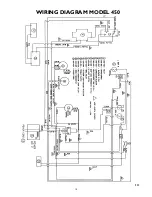
Страница 14: ...14 WIRING DIAGRAM MODEL 450 14 ...
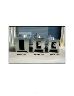
Страница 19: ...19 MODEL 450 MODEL 300 MODEL 350 ...
Страница 21: ...21 ...
Страница 22: ...22 ...
Страница 23: ...23 ...


