BRP-Rotax
REPAIR MANUAL
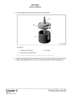
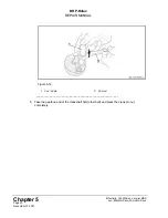
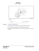
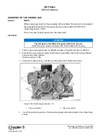
Figure 5.22
1
Crankshaft half (engine end)
2
Bottom section of the repair jig
3
Con rod pin
4
Con rod
______________________________________________________
9.
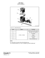
Slide the drive-end crankshaft half (1) into the top section of the repair jig (2) and hold it by
hand or with help of the M6 threaded pin (276052 only), so that it won't fall out when rotating
upside down.
10. Hold the crankshaft half as shown in following Figure and push the top section of the tool (3)
into the bottom section of the tool (2).
NOTE
A rotary movement of the con rod makes it easy to align the web hole with the con
rod pin. Make sure that the crankshaft pin is not facing towards the slot in the
crankshaft repair jig.
11. Loosen the threaded pin in the upper part of the crankshaft repair jig again and position the
thrust ring (4) on the top section of the repair jig and press the two crankshaft halves
together.
12. Measure all features of the crankshaft CS01 - CS07 and make sure each one is compliant
with the respective min/max measurements. For further information see section
NOTE
Should the crankshaft require any adjustment make sure to check the measure-
ment CS07 afterwards, see
.
Effectivity: 125 MAX evo, Junior MAX
evo, Mini MAX evo, Micro MAX evo
Page 27
November 01 2021

