background image

- 4 -

3.

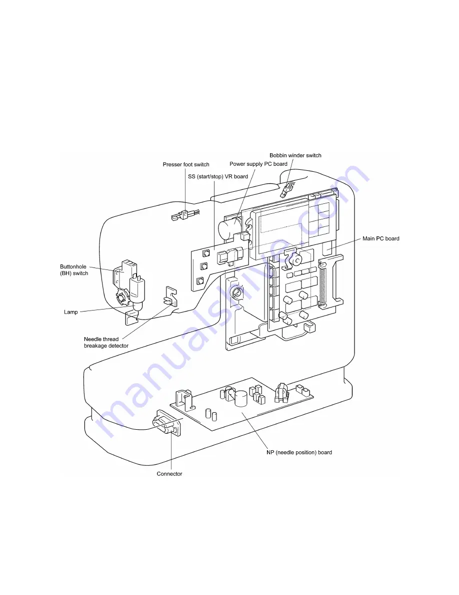
ELECTRONIC PARTS ARRANGEMENT CHART

Содержание PE-300S

Страница 1: ... 2 1999 ...

Страница 2: ...ASSEMBLY AND REASSEMBLY OF THE SEWING MACHINE 7 III HOW TO ADJUST MECHANICAL ELEMENTS 27 IV HOW TO ADJUST ELECTRONIC ELEMENTS 49 1 Always use rubber gloves when handling printed circuit boards and never touch the metal portion of a printed circuit board with bare hands 2 Keep your body earthed in order to avoid generating static electricity 3 Pack printed circuit boards in aluminum foil and avoid ...

Страница 3: ... MECHANICAL CHART 2 2 POWER TRANSMISSION CHART 3 3 ELECTRONIC PARTS ARRANGEMENT CHART 4 4 CONTROL SYSTEM BLOCK DIAGRAM 5 5 MAIN MOTOR CONTROL 6 6 PATTERN GENERATOR 6 7 OTHER ELECTRONIC COMPONENT FUNCTIONS 6 ...

Страница 4: ... 2 1 MECHANICAL CHART EMBROIDERY UNIT MECHANISM ...

Страница 5: ... 3 2 POWER TRANSMISSION CHART A Generating mechanism of needle bar thread take up lever and zigzag movements B Mechanism of feed dog and rotary hook movement ...

Страница 6: ... 4 3 ELECTRONIC PARTS ARRANGEMENT CHART ...

Страница 7: ... 5 4 CONTROL SYSTEM BLOCK DIAGRAM ...

Страница 8: ...h switch Used for backstitching and lockstitching Backstitching is performed at low speed in the reverse direction while the switch is pressed For lockstitching three stitches are made at the current needle position and then sewing stops Needle position UP DOWN switch Used to change the needle position either up ro down Touch panel Used to select pattern and input test mode number required for sew...

Страница 9: ...annot be setup when the outer components are disassembled Likewise damage can result when items are attached to the rear side of arm bed and the machine is carelessly laid on its side or knocked over When assembling or disassembling do so on top of a flexible mat For the mat use a polyethylene sheet with a thickness of about 10 20mm You may also use 2 3 layers of wadded material such as quilting ...

Страница 10: ...ve screw from plug case 9 Remove 4 screws from rear cover remove rear cover from machine Disassembly Points 3 Front and rear covers are fastened together via screws and guide in 5 places After unfastening screws first remove both guide from bed and remove front cover Next remove guide in bed section of front cover from thread guide plate While holding bottom turn and remove front cover When doing ...

Страница 11: ... 9 9 1 1 9 9 8 7 7 3 3 6 6 2 2 3 1 1 9 5 5 5 ...

Страница 12: ...thread guide plate together as one 17 Remove screw Remove zigzag connecting rod eccentric nut 18 Remove retaining ring Remove both zigzag connecting rod and Z gear together 19 Remove needle bar supporter spring remove needle bar supporter assembly 20 Remove both screws from needle bar crank Remove needle bar crank and needle bar crank rod together Disassembly Points 10 Before removing screws remov...

Страница 13: ... 11 12 11 17 20 20 15 16 19 20 18 13 14 10 10 ...

Страница 14: ...g belt together 31 Remove Allen screws remove tension pulley assembly 32 Remove spring loosen screw lift out horizontal feed shaft and remove feed link assembly 33 Remove springs from the rear and front remove vertical feed arm assembly and eccentric collar 34 Remove screw remove guide pin holder 35 Remove spring remove thread tension plate B 36 Loosen presser bar bracket screw lift out presser ba...

Страница 15: ... 13 25 2 25 1 23 36 29 29 37 32 22 22 24 24 27 27 30 30 31 31 33 33 34 32 28 36 35 26 ...

Страница 16: ...d remove drop holder assembly 39 Remove both screws and remove power supply unit Disassembly Points 39 First disconnect electrical connector lead wire of NP needle position board in front of machine from guide of power unit cover ...

Страница 17: ... 15 39 39 38 ...

Страница 18: ...ft into hole in arm bed attach needle bar clamp shaft to needle bar crank rod and attach needle bar supporter assembly Attach spring between needle bar supporter and arm bed 51 Attach needle bar supporter arm to needle bar supporter pin While keeping held in position attach H shaft holder with screw 52 Line up indicator marks on ZPM gear and Z gear see page 42 of adjustment procedures attach Z gea...

Страница 19: ... 17 Diagram A 45 1 45 2 42 53 48 52 49 50 43 42 41 44 47 47 46 40 51 ...

Страница 20: ...haft assembly and attach vertical shaft assembly with 2 bushing presser and 2 screws 62 Position so that both base line of outer rotary hook pulley and foundation hole of vertical shaft pulley are faced towards front of sewing machine and attach timing belt see page 31 of adjustment procedures 63 Adjust tension of timing belt see page 30 of adjustment procedures 64 Screw on A and B set plates 65 A...

Страница 21: ... 19 Diagram A 55 60 56 54 58 64 64 65 61 61 59 59 54 57 ...

Страница 22: ...er attach FPM holder using 2 screws 76 Attach both NP board connectors Assembly Points 67 Line up notched section of power unit cover B with rib of power unit cover A and attach see diagram A 69 First insert bobbin winder shaft and handle arm into appropriate hole and groove in rear cover Then set presser foot lifter in rear cover taking care that it does not catch onto bed section of rear cover L...

Страница 23: ... 21 diagram A 74 69 69 68 69 75 73 72 70 67 67 ...

Страница 24: ...rocedures 83 Adjust upper and lower tension see page 41 of adjustment procedures 84 Attach SS start stop VR board connectors Line front cover up to rear cover and fasten together using 3 screws 85 Attach face plate with 1 screw 86 Set inner rotary hook into outer rotary hook Attach needle plate using 2 needle plate screws Assembly Points 78 After assembling main PC board and attach front cover Mak...

Страница 25: ... 23 77 78 84 68 84 78 78 79 86 86 84 ...

Страница 26: ...n frame Separate X carriage Y carriage and bottom cover Assembly Assemble in the reverse order of disassembly Assembly Points Make sure there is space between the sensors on the X and Y shutters Make certain there is no slack between the X sensor lead wire and XPM lead wire and attach section A of bottom cover Move X carriage to the right Attach Y sensor and YPM lead wires to B section of bottom c...

Страница 27: ... 25 5 3 2 2 2 2 3 4 1 5 ...

Страница 28: ... 26 3 LEAD WIRE ARRANGEMENT ...

Страница 29: ...G HEIGHT 36 10 PRESSER BAR HEIGHT 37 11 BUTTON HOLER POSITION OF BUTTONHOLER LEVER 38 12 BOBBIN WINDER ADJUST BOBBIN WINDER SWITCH 39 13 INNER ROTARY HOOK BRACKET POSITION 40 14 INNER ROTARY HOOK TENSION 40 15 THREAD TENSION UPER THREAD TENSION 41 16 SETTING Z GEAR 42 17 FEED ADJUSTMENT GEAR BACKLASH 43 18 NEEDLE THREADER 44 19 NEEDLE THREADER CHECKING THE HOOK POSITION IN HORIZONTAL DIRECTION 44 ...

Страница 30: ...n object with a rounded tip such as a pencil or matchstick Never use a hard or sharp pointed object If the buzzer sounds once when cross number 5 is touched the adjustment has been made correctly If the buzzer sounds four when cross number 5 is touched an error has occurred In this case touch the crosses on the touch panel again in order from 1 to 5 Never press the thread cutter button during this...

Страница 31: ...ctive test mode will be entered when the numeral is pressed Test mode NO Test mode display Adjustment item page Needle down position 33 Timing of needle and rotary hook Needle bar height 35 position feed dog positions feed adjustment gear backlash Initial feed position feed adjustment gear backlash The other test modes are used for factory adjustments Test mode screen 43 35 33 5 Feed dog 43 6 3 3 ...

Страница 32: ...n tension pulley assembly 2 Move tension pulley assembly forward and backward and adjust belt tension 3 Tighten Allen screw on tension pulley assembly Adjustment Points 1 If motor belt tension is too tight there would be too much torque causing the motor to rotate slower and generate an irregular noise 2 If the motor belt tension is too loose the belt may jump and the upper shaft may not rotate sm...

Страница 33: ...Attach timing belt 2 Loosen both screws of the upper shaft gear 3 Turn pulley to raise needle bar to its uppermost position 4 Make sure that vertical shaft and outer rotary hook pulleys are positioned as indicated in 1 Then tighten both upper shaft gear screws After completing adjustments make absolutely sure to check the backlash of the upper and vertical shaft gears Rotation shutter 1 Loosen rot...

Страница 34: ...needle 3 Loosen zigzag nut screws turn eccentric nut and adjust needle drop position 4 Fasten zigzag nut screws 5 Press the marks on the screen and check needle drop position in regards to eye of the needle Adjustment Points 3 With eccentric nut the part of most eccentricity will rise towards to the top see diagram A When needle drop position is set to left needle drop position needle should be po...

Страница 35: ...er 0 1mm 7 Turn balance wheel with your hand and check that needle does not come into contact with point when needle is dropped in any position left right or center Adjustment Points Make absolutely sure to check needle clearance in both left and right needle drop positions If there is a difference in needle clearance between left and right positions move the H shaft holder to the left or right to...

Страница 36: ...4 Loosen needle bar clamp screw 5 Raise and lower needle bar and adjust distance between top of needle eye and bottom of outer rotary hook point so that it is between 1 0 1 4mm 6 Tighten needle bar clamp screw Adjustment Points When adjusting needle bar height needle bar may turn easily this could make sewing difficult When making these adjustments make sure that front of needle clamp and feed dog...

Страница 37: ...grooves of needle plate 4 If the clearance is not within the accepted range remove needle plate loosen feed dog screw and reattach feed dog 5 Press the marks on the screen and check to make sure that the feed dog does not come into contact with the needle plate 6 If feed dog does come into contact with needle plate remove needle plate reattach feed dog and repeat steps 2 5 Adjustment Points Feed d...

Страница 38: ...tandard screwdriver adjust height of feed dog so it comes between 0 9 1 1mm 4 Tighten eccentric collar screw Adjustment Points 1 If feed dog comes up too high they may scrape up against the bottom of the needle plate resulting in an abnormal noise and poor forward backward movement resulting in incorrect fabric feed or possibly failure to feed fabric 2 If feed dog is positioned too low it could re...

Страница 39: ...n presser bar guide bracket screw 4 Raise and lower presser bar and adjust so that height is within 6 0 6 5mm 5 Fasten presser bar guide bracket screw 6 Attach BH switch base board Adjustment Points Check to make sure that side of presser foot is parallel with feed dog grooves of needle plate 1 Use the J sewing foot 2 If the presser bar is not parallel with feed dog grooves the needle may come int...

Страница 40: ...heck length of finished buttonholes set a 20mm round button in the buttonholer foot and sew a bar tack stitch 5 Check to make sure that inside of vertical bar tacking is between 20 30mm Adjustment Points Pull buttonholer foot all the way out and check switch operation when you sew where two notches of buttonholer foot are returned 1 to set clearance at front of buttonholer foot A to 1 5mm set a 1 ...

Страница 41: ...ad guide back and forth Adjust bobbin winding 4 Tighten bobbin winder thread guide screw 5 Turn bobbin presser screws 2 3 revolutions turn bobbin presser and adjust bobbin winding volume see diagram A 6 Tighten bobbin presser screw Adjustment Points If bobbin winder thread guide and bobbin presser screws are not screwed on tightly enough the nuts could fall into the inside of the sewing machine so...

Страница 42: ...n inner rotary hook bracket 14 INNER ROTARY HOOK TENSION STANDARD Inner rotary hook tension should be 0 1 0 12N 10 12g when 60 spun polyester thread is slowly pulled with a tension gauge ADJUSTMENT 1 Set a bobbin would properly with 60 spun polyester thread into the inner rotary hook andpull thread slowly with tension gauge 2 Use a screwdriver to turn spring adjustment screw to the left and right ...

Страница 43: ... foot lifter run 60 spun polyester thread through thread tension disk 3 Lower presser foot lifter slowly pull thread downwards with tension gauge 4 Turn thread tension adjusting screw set upper thread tension so that it falls into the range of 0 33 0 38N 33 38g When carrying out these adjustments do not pass thread through thread guide plate It should only pass through the thread tension disk Afte...

Страница 44: ...lse motor Z gear 4 Line up indicator marks on ZPM gear and Z gear and attach Z gear Adjustment Points 1 If release cam indicator marks do not line up properly thread tension disk may fail to open during long jumps in embroidery when embroidery hoop moves over a substantial distance resulting in possible thread and needle breakage 2 If ZPM gear and Z gear indicator marks do not line up it could res...

Страница 45: ...n both FPM screws 6 Fasten both screws on set plate C of NP board 7 Select test mode 6 initial feed position move feed dog back to set them in their initial position 8 Make sure that clearance between surface of FPM gear and rubber stop of initial plate is within 1 0 2 0mm 9 While set in test mode 5 feed dog position repeatedly depress and marks and check that F gear moves freely Adjustment Points...

Страница 46: ...ead to imperfect performance and possibly even breakage of needle threader itself 3 Lower presser foot when using needle threader 4 Nylon transparent thread can be used with 14 16 sewing machine needles regardless of what is listed on chart below 5 Do not turn the balance wheel when using needle threader 6 Do not lower needle threader lever when operating sewing machine Doing so could break the ne...

Страница 47: ...up D cut face of new needle threader and needle threader shaft as indicated by A in the diagram below 4 Attach needle threader guide so that it fits into groove of shaft 21 NEEDLE THREADER CHECKING THE HOOK IN STANDARD POSITION vertical direction in relation to eye of the needle Clearance between top of hook and top of needle eye should be 0mm Needle threader can be used when needle point is raise...

Страница 48: ...ot be held by the positioning supporter so the lever will not move and thread the needle even if needle threader lever is in lowest position figure 1 If this is the case loosen positioning supporter screw move the positioning supporter slightly to the left to make it parallel Furthermore if positioning supporter is turned to far to the left so that it is not parallel positioning supporter may come...

Страница 49: ...h a force of 100g after the X carriage unit is moved all the way to the right ADJUSTMENT 1 Move X carriage assembly all the way to the right 2 Loosen screw of X tension pulley holder 3 Move X tension pulley holder to the right and left and adjust belt tension 4 Tighten screw of X tension pulley holder Adjustment Points If belt tension is too loose or too tight it could result in poor stitching or ...

Страница 50: ...r with a force of 100g after the Y carriage is moved all the way forward ADJUSTMENT 1 Move Y carriage assembly all the way forward 2 Loosen screw of Y tension pulley holder 3 Move Y tension pulley holder back and forth to adjust belt tension 4 Tighten screw of Y tension pulley holder Adjustment Points If belt tension is too weak or too strong it could result in poor stitching or faulty embroidery ...

Страница 51: ...f main motor is not stable maximum speed operation is not possible or speed cannot be adjusted 51 6 Correct patterns are not created 51 7 Buttonholes are not stitched correctly 51 8 Manual operation of feed and zigzag pulse motors is not possible 51 9 Vertical movement of needle bar and backstitch operation are abnormal 51 10 Foot controller does not operate normally when depressed 52 11 LCD does ...

Страница 52: ...rmal for the pulse motors which do not return to the home position Zigzag CN13 1 3 2 3 4 5 4 6 8 10 Ω Feed CN13 1 3 2 3 4 5 4 6 8 10 Ω Horizontal CN13 1 3 2 3 4 5 4 6 8 10 Ω 2 Set the home position for the same pulse motors irrespective of needle position 3 Remove power source connector CN13 and check that voltage between pins 2 and 3 is as indicated below Between pins 2 and 3 DC 18 30V 4 Others 1...

Страница 53: ...ween pins 4 5 of the junction board BH connector CN10 normal When buttonhole lever is lowered 1 Ω or less When buttonhole lever is raised 3 When the buttonhole lever is lowered and in the conditions below is the resistance between pins 1 2 and 2 3 of the junction board connector CN10 normal Between 1 2 Between 2 3 Button hole lever is pulled forward 1 Ω or less Buttonhole lever is pushed back 1 Ω ...

Страница 54: ...long thread paths and thread conditions are set as follows is voltage between pins 1 7 of SSVR board connector CN4 as follows When thread tension is tightened DC 0V When thread tension is loosened DC 5V 3 Others 1 If condition does not change after adjusting thread take up spring replace needle thread breakage detecting PC board 2 Exchange SS VR PC board assembly 3 Replace main PC board assembly 1...

Страница 55: ...d Speed sensor Power cord 100V Foot controller jack Main motor Power switch Transformer Main PC board CN7 Main PC board CN6 NP board CN1 NP board CN2 Fuse Lamp Embroidery unit connector Feed pulse motor Main motor control Zigzag pulse motor NP sensor Speed sensor Touch panel Power source 2 ...

Страница 56: ...d breakage detector Needle thread breakage detector board X initial sensor board Y initial sensor board Main PC board CN9 Main PC board CN13 Foot controller NP sensor Main PC board NP board Speed VR Needle thread breakage detector Power source 1 ...

Страница 57: ...PE 300S H8080132 ...

Отзывы: