- 33 -
6.
TIMING OF NEEDLE AND ROTARY HOOK (CLEARANCE BETWEEN THE
NEEDLE AND THE ROTARY HOOK POINT)
STANDARD
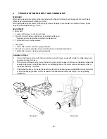
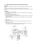
While in test mode (3) 3-point needle drop, select left needle drop. When the needle is raised 2.75-3.15mm from
its lowest position, the rotary hook point should clear the outer side of the needle. When using a #11 needle, the
clearance between the needle and outer rotary hook point should be under 0.1mm.
ADJUSTMENT
1.
Set machine to test mode and select (3) 3-point needle drop.
2.
Press the
mark on the screen to move the needle drop position to the left.
3.
Loosen both vertical shaft pulley screws.
4.
Adjust so that when needle (#11 needle) is raised 2.75-3.15mm from lowest position, outer rotary hook point
clears outside of needle.
5.
Tighten both vertical shaft pulley screws.
6.
Turn needle clearance adjusting screw, and adjust clearance between back of needle and point so that it is
under 0.1mm.
7.
Turn balance wheel with your hand, and check that needle does not come into contact with point when needle is
dropped in any position; left, right or center.
Adjustment Points
* Make absolutely sure to check needle clearance in both left and right needle drop positions. If there is a
difference in needle clearance between left and right positions, move the H shaft holder to the left or
right to adjust.
•
If needle clearance is greater in the left drop position than the right, slide the H shaft holder to the left.
•
If needle clearance is greater in the right drop position than the left, slide the H shaft holder to the right.
(1)
If needle clearance is too great, skipped stitches may result.
(2)
If needle clearance is too narrow, an abnormal metallic noise and needle breakage could result.
(3)
If needle does not rise high enough, skipped stitches, split thread and thread breakage could result.
(4)
If the needle rises too far, loops may form in the thread resulting in skipped stitches, split thread and thread
breakage.
3-point needle drop screen
5
3
Under 0mm
Under 0mm
6
6
2.75-3.15mm
0mm
Содержание PE-300S
Страница 1: ... 2 1999 ...
Страница 4: ... 2 1 MECHANICAL CHART EMBROIDERY UNIT MECHANISM ...
Страница 6: ... 4 3 ELECTRONIC PARTS ARRANGEMENT CHART ...
Страница 7: ... 5 4 CONTROL SYSTEM BLOCK DIAGRAM ...
Страница 11: ... 9 9 1 1 9 9 8 7 7 3 3 6 6 2 2 3 1 1 9 5 5 5 ...
Страница 13: ... 11 12 11 17 20 20 15 16 19 20 18 13 14 10 10 ...
Страница 15: ... 13 25 2 25 1 23 36 29 29 37 32 22 22 24 24 27 27 30 30 31 31 33 33 34 32 28 36 35 26 ...
Страница 17: ... 15 39 39 38 ...
Страница 19: ... 17 Diagram A 45 1 45 2 42 53 48 52 49 50 43 42 41 44 47 47 46 40 51 ...
Страница 21: ... 19 Diagram A 55 60 56 54 58 64 64 65 61 61 59 59 54 57 ...
Страница 23: ... 21 diagram A 74 69 69 68 69 75 73 72 70 67 67 ...
Страница 25: ... 23 77 78 84 68 84 78 78 79 86 86 84 ...
Страница 27: ... 25 5 3 2 2 2 2 3 4 1 5 ...
Страница 28: ... 26 3 LEAD WIRE ARRANGEMENT ...
Страница 57: ...PE 300S H8080132 ...


