V-38
4.
HOW TO USE DIAG. (C/E) MODE
4.1
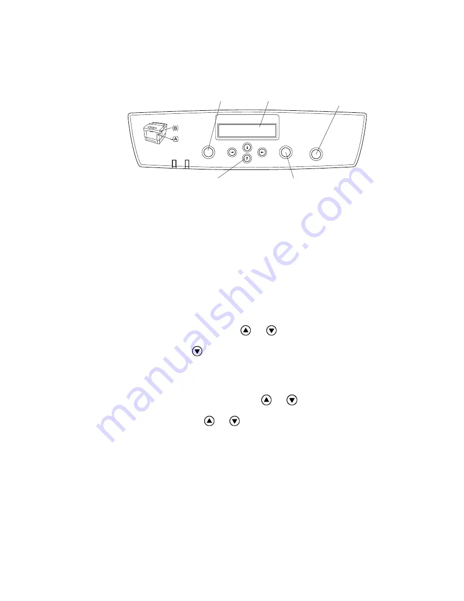
Roles of the Control Panel in Diag. (C/E) Mode
(Note: Control panel display may differ depending upon the machine configuration.)
Ready Alarm
Menu
Form Feed
Set
Job
Cancel
Back
Fig.5-3
1. LCD panel: Displaying a diagnostic item and its result.
2. Up/Down buttons: Selecting a diagnostic item.
Selecting data at parameter setting.
3. Form Feed/Set button: Determining a diagnostic item.
Executing a diagnosis.
Determining a parameter at parameter setting.
4. Job Cancel/Back button: Resetting a diagnostic item.
(Returning to the menu one level higher)
Terminating each digital input/output test.
5. Menu button: Exiting digital input/output test mode.
6. Right button: Printing registration adjustment data at parameter setting for
determination.
4.2
Entering Diag. (C/E) Mode
1. Turn the power on while pressing the
and
buttons together.
2. Enter the password.
(Password: Press the
button twice and the Form Feed/Set button.)
4.3
Exiting Diag. (C/E) Mode
1. Stop the current diagnosis.
2. Press the Job Cancel/Back button to return to the top of the diagnostic menu.
3. Select [CE Maintenance Complete] with the
and
buttons.
4. Press the Form Feed/Set button to determine the selection.
5. Select [Complete] with the
and
buttons.
6. Press the Form Feed/Set button to determine the selection.
7. Exit Diag. (C/E) mode. (Reboot in Normal mode.)
4.4
Diag. (C/E) Mode Functions
In Diag. (C/E) mode, the printer provides the following six functions:
1. ESS
diagnosis
2. IOT
diagnosis
3. Print
Info
4. Complete
5. Installation
set
6. Test
7. Parameter
4. Job Cancel/Back button
1. LCD
5.Menu
3.Form Feed/Set button
2.Up/Down button
Содержание HL-4200CN
Страница 21: ...CHAPTER I SPECIFICATIONS ...
Страница 42: ...CHAPTER II INSTALLATION ...
Страница 54: ...II 11 12 Close the front cover Fig 2 27 ...
Страница 62: ...CHAPTER III STRUCTURE OF SYSTEM COMPONENTS ...
Страница 98: ...III 34 5 7 2 Reference diagram Transfer Roll Cartridge ASSY FUSER ASSY Exit Sensor FAN FUSER Fig 3 40 ...
Страница 115: ...CHAPTER IV ASSEMBLY DISASSEMBLY ...
Страница 166: ... IV 48 Magenta Fig 4 86 Cyan Fig 4 87 Holder toner cartridge ASSY 2 Holder toner cartridge ASSY 3 ...
Страница 167: ... IV 49 Black Fig 4 88 Holder toner cartridge ASSY 4 ...
Страница 204: ...CHAPTER V TROUBLESHOOTING ...
Страница 279: ...V 73 10 IMAGE QUALITY SPECIFICATIONS 10 1 Parallelism Fig 5 13 10 2 Diagonal Fig 5 14 10 3 Skew Fig 5 15 ...
Страница 280: ...V 74 10 4 Straightness Fig 5 16 10 5 Magnification Error Fig 5 17 10 6 Registration Fig 5 18 ...
Страница 281: ...V 75 10 7 Guaranteed Printing Area Fig 5 19 ...
Страница 297: ...CHAPTER VI DIAGRAMS ...
Страница 341: ...CHAPTER VII PLUG JACK P J CONNECTOR LOCATIONS ...
Страница 342: ...CONTENTS CHAPTER VII PLUG JACK P J CONNECTOR LOCATIONS VII 1 1 LIST OF P J VII 1 2 P J LAYOUT DIAGRAM VII 4 ...
Страница 346: ...VII 4 2 P J LAYOUT DIAGRAM ...
Страница 347: ...VII 5 ...
Страница 348: ...VII 6 ...
Страница 349: ...VII 7 ...
Страница 350: ...APPENDIX ...
Страница 359: ...The actual life is over than catalog specification But as you may know we are including some margin ...


