V-16
Code No.
LCD Message
Description of Message
16-3
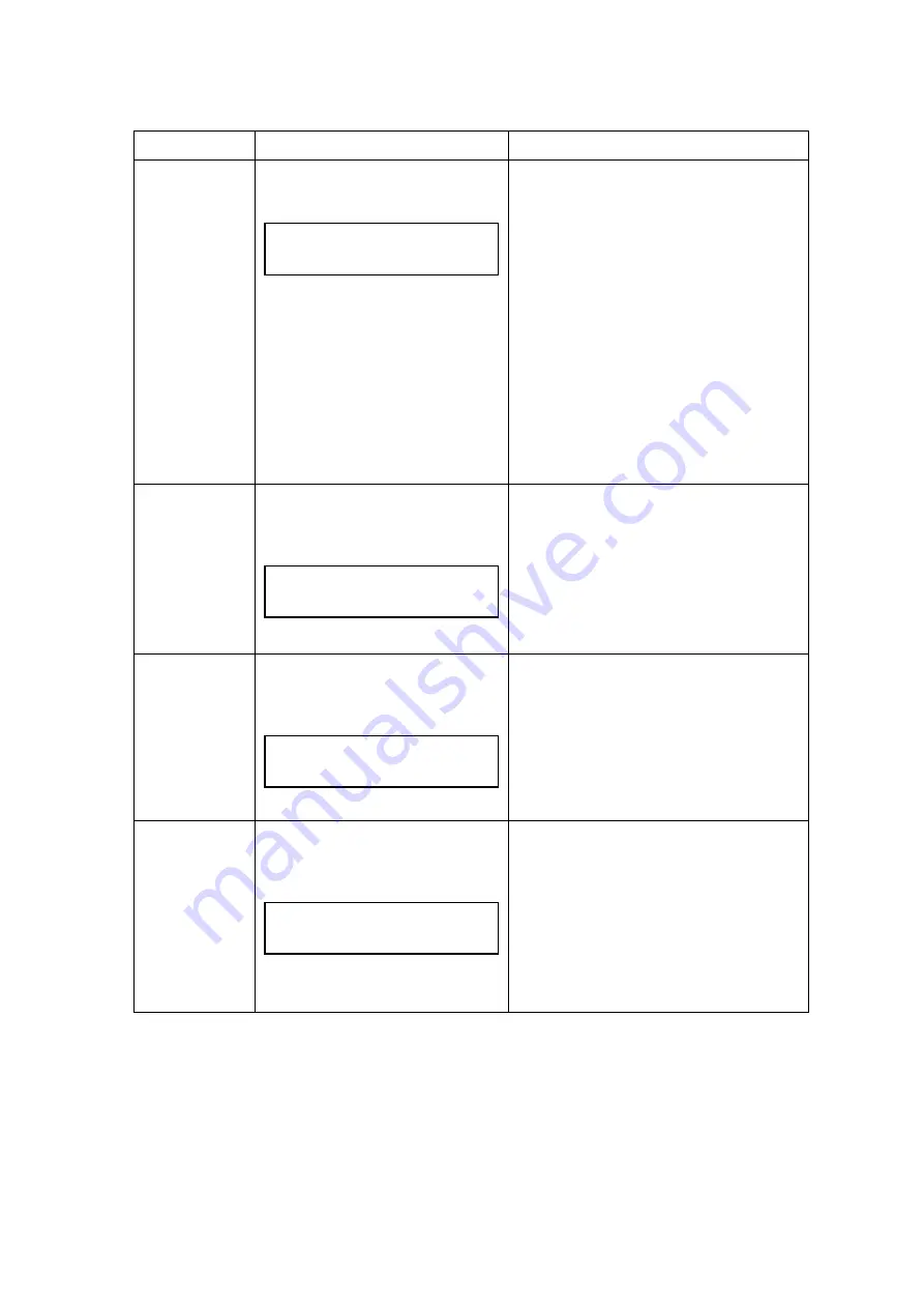
ALIGN TONER CG
16 ALIGN [*5]
TONER CG [*4]
x
The engine is idling.
x
The Power LED is lit.
[*5]: The color of the incorrectly installed
toner cartridge will be indicated as
follows;
Y:
Yellow
M:
Magenta
C:
Cyan
K:
Black
x
Reinstall the toner cartridge correctly.
x
This message will be automatically
cleared by open & close operation of
the front cover.
16-4
ALIGN BELT CG
16 ALIGN BELT CG
[*4]
x
The engine is standstill.
x
The Power LED is lit.
x
The OPC belt cartridge is not
installed. Reconfirm the installation
status of the OPC belt cartridge.
x
This message will be automatically
cleared by open & close operation of
the paper exit cover or front cover.
16-5
ALIGN LFU
16 ALIGN LFU
[*4]
x
Engine stands by as “ALIGN LFU”
status.
x
Turn the power off, and then connect
the harness between the engine and
LFU.
x
Turn the power on. If the warming-up
process starts, it means that proper
connection is made.
16-6
ALIGN TRANSFER ROLLER
16 ALIGN TRANSFER
ROLLER [*4]
x
Engine stands by as “ALIGN
TRANSFER ROLLER” status.
x
The Power LED is lit.
x
Transfer roller is not installed.
Reconfirm the installation status of
transfer roller.
x
This message will be automatically
cleared by open & close operation of
back cover (L).
Содержание HL-2600CN Series
Страница 14: ...viii 3 Rating Label For US For Europe Jam label ...
Страница 16: ... 37 5 352 8 7 287 1 ...
Страница 26: ...CHAPTER II SPECIFICATIONS ...
Страница 38: ... 37 5 167 7 21 ...
Страница 50: ...CHAPTER IV STRUCTURE OF SYSTEM COMPONENTS ...
Страница 64: ...IV 13 CBV DBV Fig 4 15 Y M C K Fig 4 16 Developer roller Toner OPC Belt Toner M Exposing Developing ...
Страница 99: ...Main PCB Circuit Diagram 1 8 CODE B512137CIR 1 8 LJ8907001 IV 48 NAME ...
Страница 100: ...Main PCB Circuit Diagram 2 8 CODE B512137CIR 2 8 LJ8907001 IV 49 NAME ...
Страница 101: ...Main PCB Circuit Diagram 3 8 CODE B512137CIR 3 8 LJ8907001 IV 50 NAME ...
Страница 102: ...Main PCB Circuit Diagram 4 8 CODE B512137CIR 4 8 LJ8907001 IV 51 NAME ...
Страница 103: ...Main PCB Circuit Diagram 5 8 CODE B512137CIR 5 8 LJ8907001 IV 52 NAME ...
Страница 104: ...Main PCB Circuit Diagram 6 8 CODE B512137CIR 6 8 LJ8907001 IV 53 NAME ...
Страница 105: ...Main PCB Circuit Diagram 7 8 CODE B512137CIR 7 8 LJ8907001 IV 54 NAME ...
Страница 106: ...Main PCB Circuit Diagram 8 8 CODE B512137CIR 8 8 LJ8907001 IV 55 NAME ...
Страница 108: ...IV 57 Layout of Connector Pin Assignment Power Supply Unit Fig 4 40 ...
Страница 112: ...IV 61 Layout of Connector Pin Assignment High Voltage Power Supply Unit Fig 4 41 ...
Страница 124: ...CHAPTER V CONTROL PANEL OPERATION ...
Страница 170: ...CHAPTER VI 3 5 2 0 17 1 1 ...
Страница 210: ...CHAPTER VII 6 66 0 ...
Страница 286: ... 37 5 9 7528 6 227 1 ...
Страница 330: ...9 5 IMAGE FAILURE 1 2 3 4 5 6 7 8 9 a 9 b 10 11 12 13 14 ...
Страница 331: ...9 15 a 15 b 16 17 18 19 20 21 22 23 24 25 26 27 28 Fig 8 2 ...
Страница 351: ...A 4 6 Transfer Drum Hand writing X X X X X X 7 1 2 3 Location DATE MONTH SERIAL NO YEAR ...
Страница 366: ...A 19 6 Fix the four joints then band the box with two plastic bands P P band Joint ...


