Brother HL-1240 Скачать руководство пользователя страница 263

CHAPTER 2 OPTIONS

2-11

How to add extra Memory (For HL-1250 Only)

The HL-1240

 printer has 2 Mbyte of standard memory and is not able to be

upgraded with additional memory.

The HL-1250

 printer has 4 Mbyte of standard memory and a slot for optional

additional memory. The memory can be expanded up to a total of 36 Mbytes by
installing a commercially available single in-line memory module (SIMM).

Additional memory is useful and may be necessary if you are using the Page
Protection function.

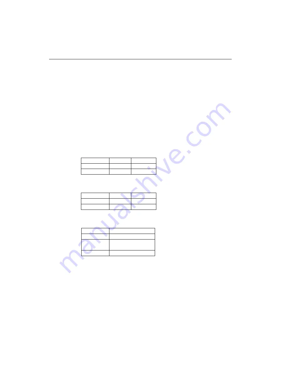
Minimum Memory Recommendation (including resident memory)

Page Protect = AUTO or Off

300 dpi

600 dpi

Letter/A4

2 MB

2 MB

Legal

2 MB

2 MB

Page Protection = Letter, A4, or Legal

300 dpi

600 dpi

Letter/A4

2 MB

6 MB

Legal

3 MB

6 MB

This printer can accept memory SIMM with the following specifications:

Speed

60 nsec - 80 nsec

Pin Type

72 pin

Height

35.00 mm (1.38”) or
less

Output

32 bit or 36 bit

Содержание HL-1240

Страница 1: ......

Страница 2: ...stered in the United States and other countries and True Type is a trademark of Apple computer Inc Epson is a registered trademark and FX 80 and FX 850 are trademarks of Seiko Epson Corporation Hewlett Packard is a registered trademark and HP Laser Jet is a trademark of Hewlett Packard Company IBM IBM PC and Proprinter are registered trademarks of International Business Machines Corporation Micros...

Страница 3: ...ng information CHAPTER 4 DISASSEMBLY AND RE ASSEMBLY Procedures for disassembling and re assembling the mechanical system CHAPTER 5 MAINTENANCE Periodical replacements parts consumable parts etc CHAPTER 6 TROUBLESHOOTING Reference values and adjustments troubleshooting image defects troubleshooting malfunctions etc APPENDICES Serial No descriptions Drum life page counter Diameter circumference of ...

Страница 4: ...2 1 1 2 Environment 2 1 1 3 System Requirements for Brother Printer Solution for Windows 2 1 2 UNPACKING 2 2 3 INSTALL THE PRINTER 2 3 3 1 For Windows Users 2 3 3 2 For Windows Users with No CD ROM Drive 2 5 3 2 1 Install the drum unit 2 5 3 2 2 Load paper 2 5 3 2 3 Print a test page 2 5 3 2 4 Connect the printer and the computer 2 6 3 2 5 Install the printer driver from floppy disk 2 6 3 3 Using ...

Страница 5: ...ock Diagram 3 1 1 2 Main PCB Block Diagram 3 3 1 3 Main PCB 3 5 1 3 1 ASIC 3 5 1 3 2 ROM 3 8 1 3 3 DRAM 3 9 1 3 4 Optional RAM 3 11 1 3 5 Optional serial I O 3 12 1 3 6 EEPROM 3 12 1 3 7 Reset circuit 3 13 1 3 8 Engine I O 3 14 1 4 Engine PCB 3 14 1 5 Power Supply 3 15 1 5 1 Low voltage Power Supply 3 15 1 5 2 High voltage Power Supply 3 16 2 MECHANICS 3 17 2 1 Overview of Printing Mechanism 3 17 ...

Страница 6: ...0 only 4 26 3 13 Low voltage Power Supply PCB ASSY 4 27 3 14 Engine PCB ASSY High voltage Power Supply PCB ASSY 4 28 3 15 Panel PCB ASSY 4 30 3 16 Solenoid ASSY 4 30 3 17 Fan Motor ASSY 4 33 3 18 Toner Sensor PCB ASSY Light Emission 4 34 3 19 Toner Sensor PCB ASSY Light Reception 4 34 3 20 Paper Pick up Roller ASSY 4 35 3 21 Paper Feed Roller ASSY 4 36 4 PACKING 4 37 CHAPTER 5 PERIODIC MAINTENANCE...

Страница 7: ...G PROBLEMS 6 14 6 MALFUNCTIONS 6 18 7 IMAGE DEFECTS 6 23 7 1 Image Defect Examples 6 23 7 2 Troubleshooting Image Defect 6 24 7 3 Location of Grounding Contacts 6 41 7 3 1 Drum unit 6 41 7 3 2 Printer body paper cassette 6 41 8 INCORRECT PRINTOUT 6 42 9 INSPECTION MODE 6 45 9 1 Test Print Mode 6 45 9 2 Inspection Mode 6 46 APPENDICES 1 SERIAL NO DESCRIPTIONS A 1 2 DIAMETER CIRCUMFERENCE OF ROLLERS...

Страница 8: ...1 14 MAIN PCB CIRCUIT DIAGRAM HL 1250 3 5 A 22 15 MAIN PCB CIRCUIT DIAGRAM HL 1250 4 5 A 23 16 MAIN PCB CIRCUIT DIAGRAM HL 1250 5 5 A 24 17 ENGINE PCB CIRCUIT DIAGRAM A 25 18 LOW VOLTAGE POWER SUPPLY PCB CIRCUIT DIAGRAM 110 120V A 26 19 LOW VOLTAGE POWER SUPPLY PCB CIRCUIT DIAGRAM 220 240V A 27 20 HIGH VOLTAGE POWER SUPPLY PCB CIRCUIT DIAGRAM A 28 INDEX ...

Страница 9: ...fter August 2 1976 Compliance is mandatory for products marketed in the United States One of the following labels on the back of the printer indicates compliance with the FDA regulations and must be attached to laser products marketed in the United States The label for Japanese manufactured products MANUFACTURED K BROTHER INDUSTRIES LTD 15 1 Naeshiro cho Mizuho ku Nagoya 467 8561 Japan This produc...

Страница 10: ... Since the variable resistor in the laser unit is adjusted in accordance with the standards never touch it Caution Use of controls adjustments or performance of procedures other than those specified in this manual may result in hazardous radiation exposure For Finland and Sweden LUOKAN 1 LASERLAITE KLASS 1 LASER APPARAT Varoitus Laitteen käyttäminen muulla kuin tässä käyttöohjeessa mainitulla tava...

Страница 11: ...amage the eyes Since the beam is invisible the following caution label is attached on the laser unit CAUTION INVISIBLE LASER RADIATION WHEN OPEN AND INTERLOCK DEFEATED AVOID DIRECT EXPOSURE TO BEAM CLASS 3B LASER PRODUCT ADVARSEL USYNLIG LASER STRÅLING NÅR KABINETLÅGET STÅR ÅBENT UNGDÅ DIREKTE UDSÆTTELSE FOR STRÅLING KLASSE 3B LASER VARNING OSYNLIG LASERSTRÅLNING NÄR DENNA DEL ÄR ÖPPNAD OCH SPÄRRA...

Страница 12: ...rious kinds of WARNING messages included in this manual WARNING Always turn off the power switch and unplug the power cord from the power outlet before accessing any parts inside the printer WARNING Some parts inside the printer are extremely hot immediately after the printer is used When opening the front cover or rear cover to access any parts inside the printer never touch the red colored parts...

Страница 13: ...y scale adjustment resolution water mark and many layout functions You can easily setup these print options through the Printer Setup Menu Printer Status Monitor with Bi directional Parallel Interface The printer driver can monitor the status of your printer using bi directional parallel communications IEEE 1284 bi directional parallel printer cable is recommended The printer status monitor progra...

Страница 14: ...n or HP and IBM If you want to set the printer emulation you can do it using the Remote Printer Console Program High Resolution Control Advanced Photoscale Technology for HL 1250 only High Resolution Control HRC technology provides clear and crisp printouts Use this function to get smooth text print quality Advanced Photoscale Technology APT enables the printer to print graphics in 256 grayscales ...

Страница 15: ...per guides Paper cassette Control panel Tray extension flap Front cover Power switch Manual feed slot Rear cover Paper indicator USB interface connector Power switch Parallel interface connector Rear cover AC power inlet USB interface connector Modular jack for Lower Tray Unit AC power inlet Parallel interface connector ...

Страница 16: ...cassette Warm up Max 45 seconds at 23 C 73 4 F First print 15 seconds when loading A4 or Letter size paper from the paper cassette Print media Toner cartridge Life expectancy 3 000 pages cartridge Standard cartridge 6 000 pages cartridge High capacity cartridge when printing A4 or Letter size paper at 5 print coverage Developer Drum unit Life expectancy 20 000 pages drum unit NOTE Print speed vari...

Страница 17: ...60 Hz Europe and Australia AC 220 to 240V 50 Hz 60 Hz Power consumption Printing peak 940 W or less Printing average 340 W or less Standing by 80 W or less Sleep 5 W or less HL 1240 6 W or less HL 1250 Noise Printing 49 dB A or less Standing by 27 dB A or less Temperature Operating 10 to 32 5 C 50 to 90 5 F Non operating 0 to 40 C 38 to 104 F Storage 20 to 40 C 4 to 104 F Humidity Operating 20 to ...

Страница 18: ...57 14 inches Envelopes DL C5 COM10 Monarch B5 ISO Organizers J K L sizes of DAY TIMER Labels A4 Letter Transparencies A4 Letter Other sizes 70 216 x 116 356 mm 2 75 8 5 x 4 57 14 inches Optional lower paper cassette HL 1250 only Normal paper Transparencies A4 Letter B5 ISO A5 Executive Legal NOTE Legal size paper can be printed with the standard paper cassette or the optional lower cassette for th...

Страница 19: ...are designed for use in laser printers Avoid feeding labels with the carrier sheet exposed or the printer will be damaged Before loading paper with holes such as organizer sheets be sure to fan the stack well Do not use organizer sheets that are stuck together The glue that is used might caused damaged to the printer When printing on the back of pre printed paper if the paper is curled be sure to ...

Страница 20: ...over at the rear of the printer Face down Delivery with the printed face of the paper downwards Face up Delivery with the printed face of the paper upwards 3 5 Printing Area 3 5 1 Effective printing area The effective printing area means the area within which the printing of all the data received without any omissions can be guaranteed 4 23mm 4 23mm 208mm 2 400 80 characters 25 25 NOTE The units i...

Страница 21: ...CHAPTER 1 GENERAL 1 9 3 5 2 Print guaranteed area A E C E B D F F The values above vary depending on the paper size For details see the table on the next page ...

Страница 22: ...mm 3 66 1 098 dots 140 0 mm 5 51 1 654 dots Organizer J size 69 85 mm 2 75 825 dots 116 0 mm 4 57 1 370 dots 56 2 mm 2 21 675 dots 107 5 mm 4 23 1 270 dots 6 35 mm 0 25 75 dots Organizer K size 95 25 mm 3 75 1 125 dots 171 45 mm 6 75 2 025 dots 86 78 mm 3 42 975 dots 162 98 mm 6 42 1 925 dots Organizer L size 139 7 mm 5 5 1 650 dots 215 9 mm 8 5 2 550 dots 131 23 mm 5 17 1 500 dots 207 43 mm 8 17 ...

Страница 23: ...lean Do not place the printer in a dusty place Do not place the printer where the ventilation hole of the printer is blocked Keep approximately 100 mm 4 inches between the ventilation hole and the wall Do not place the printer where it is exposed to direct sunlight Use a blind or a heavy curtain to protect the printer from direct sunlight when the printer is unavoidably set up near a window Do not...

Страница 24: ...When unpacking the printer check to see that all of the following components are included in the carton Fig 2 1 NOTE Components may vary depending on the country AC cord Printer Paper cassette Drum unit with Toner cartridge included Documents CD ROM Floppy disk ...

Страница 25: ...rive 3 1 For Windows Users 1 Turn on your PC power Close all the applications running on your PC 2 Insert the supplied CD ROM into the CD ROM drive 3 The opening screen will appear automatically in Windows 95 98 NT4 0 NOTE If the opening screen does not appear Click Start and select Run Then type D START in the command line box and click OK If your CD ROM drive is not D type the correct drive lett...

Страница 26: ...lick the NOW button you can install the printer driver immediately 10 After the printer driver has been installed the HL 1240 or HL 1250 window will appear Follow the on screen messages to complete the installation Fig 2 7 If your printer is connected using a parallel interface cable the setup is now completed If you want to connect your printer using a USB interface cable refer to Subsection 3 3 ...

Страница 27: ...nto the printer until it snaps into place and close the front cover 3 2 2 Load paper 1 Pull the paper cassette completely out of the printer 2 Slide the paper guides to the paper size you want until they snap into a slot Fig 2 9 Fig 2 9 3 Load paper into the paper cassette Check that paper is flat placed Fig 2 10 Paper should be loaded up to the lines on the sliding guide 4 Re install the paper ca...

Страница 28: ... Fig 2 13 3 2 5 Install the printer driver from floppy disk 1 Turn on the computer power If the Add New Hardware Wizard window appears click the Cancel button 2 Insert the supplied floppy disk into the floppy disk drive 3 Install the printer driver using the Setup exe file In Windows 95 98 i Click the Start button and select Run ii Type A SETUP and click OK If your floppy disk drive is not A inser...

Страница 29: ...at the printer power switch is on 2 Connect the USB interface cable to the computer then connect it to the printer Fig 2 14 Fig 2 14 3 3 2 Install the USB driver 1 The Add New Hardware Wizard window will appear Click the Next button Fig 2 15 2 Select Search for the best driver for your device Click the Next button Fig 2 16 USB interface cable ...

Страница 30: ...e supplied CD ROM into the CD ROM drive and select CD ROM drive Click the Next button Fig 2 17 4 Click the Next button then the USB driver will be installed Fig 2 18 5 Click the Finish button Fig 2 19 6 Click the Yes button then your PC will re start Fig 2 20 ...

Страница 31: ...Properties dialog box The setup is now completed Fig 2 21 NOTE Both the parallel cable and USB interface cable can be connected to the printer at the same time 3 4 For Macintosh iMac and Power Macintosh with USB Users Only You can setup the printer following the Initial Setup instructions on the supplied CD ROM 1 Turn on the computer power then insert the CD ROM into the CD ROM drive The window sh...

Страница 32: ... feed slot follow the steps below 1 Select the manual feed mode in the printer driver and send the print data to the printer NOTE A NO PAPER message is shown in the status monitor until a sheet of paper is inserted into the manual feed slot 2 Set the width of the manual feed slot paper guides using both hands to the paper width to be used Fig 2 23 Fig 2 23 3 Insert the paper into the manual feed s...

Страница 33: ...ause wrinkling If paper is curled straighten it and then set it into the paper cassette The paper type should be regular paper Do not use bond paper When setting paper into the paper cassette empty the cassette first then insert the printed paper only printed side face up Do not add the printed paper onto the top of the unprinted paper stack If the paper is not feeding correctly the paper might be...

Страница 34: ...manual feed mode from the driver 2 Using both hands insert the paper into the manual feed slot with the side to be printed first facing upwards Follow the instructions on the computer screen 3 Repeat action 2 until you have printed all the even numbered pages 4 Remove the printed even numbered pages from the output tray 5 Re insert them in order into the manual feed slot loading the paper with the...

Страница 35: ...ives data or when you press the control panel button Blinking Blinking at 1 second intervals The printer is warming up Blinking at 2 seconds intervals The printer is cooling down and stops printing until the internal temperature of the printer lowers ON The printer is ready to print This LED also works as the Paper LED with the Alarm LED They blink simultaneously to indicate a paper error See Subs...

Страница 36: ...ls in CHAPTER 6 for details Error Action Toner low Indicates that the toner cartridge is nearly empty Purchase a new toner cartridge ready for when the Toner empty error is indicated Toner empty Replace the toner cartridge with a new one 5 3 Drum LED Indications The Drum LED indicates the drum unit is nearly at the end of its life LED Printer status OFF The drum unit can be used ON The drum unit i...

Страница 37: ... timeout is 5 minutes and it is automatically adjusted to the most suitable time out setting depending on the frequency of your printer use Intelligent Sleep Mode While the printer is in sleep mode all the LEDs are off and it is as if it was turned off but the printer can still receive data from the computer Receiving a print file or document automatically wakes up the printer to start printing Pr...

Страница 38: ...PERATION 2 16 5 6 2 Test print mode The printer incorporates various test print modes The printer enters into each test print mode by panel button operation For details on test print mode see Subsection 9 1 Test Print Mode in CHAPTER 6 ...

Страница 39: ...gine control block Operation block Control panel Control system Low voltage power supply block High voltage power supply block Laser unit Drive block DC motor Drum unit Transfer block Drum Charging block External device Paper tray unit Paper cassette Manual feed Fixing unit Paper eject block Paper feed system Image generation system RAM 2MB Paper dust cleaner block Developing block Toner cartridge...

Страница 40: ...tion block Operation panel Control system Low voltage power supply block High voltage power supply block Laser unit Drive block DC motor Drum unit Transfer block Drum Charging block External device External device Paper tray unit Paper cassette Manual feed Fixing unit Paper eject block Paper feed system Image generation system Interface block Parallel USB RAM 4MB Paper dust cleaner block Developin...

Страница 41: ... PCB of the HL 1240 printer Reset Circuit Program Font ROM 1 0 Mbytes RAM 2 0 Mbytes EEPROM 128 8 bits A S I C Oscillator 32 7MHz Address Decoder DRAM Control Timer FIFO CDCC Parallel I O Soft Support EEPROM I O Engine Control I O To Engine PCB CPU Core MB86833 BUS INT To PC USB I O To PC Fig 3 3 HL 1240 ...

Страница 42: ...gram Font ROM 4 0 Mbytes RAM 4 0 Mbytes Option RAM SIMM max 32Mbytes Option Serial I O RS232C RS422A EEPROM 512 x 8 bits CPU Core MB86832 A S I C Oscillator 32 7MHz Address Decoder DRAM Control Timer FIFO CDCC Parallel I O Soft Support EEPROM I O Engine Control I O To Engine PCB BUS INT To PC USB I O To PC Fig 3 4 HL 1250 ...

Страница 43: ...cation with external devices are described below 1 IEEE1284 Stores the data received from the PC into DRAM as controlled by the DMA controller It is applicable to both normal receiving and bi directional communication nibble mode byte mode ECP mode 2 USB interface Stores the data received from the PC into DRAM as controlled by the DMA controller The transmission speed is 12Mbps 3 Engine GA transfe...

Страница 44: ...ith external devices are described below 1 IEEE1284 Stores the data received from the PC into DRAM as controlled by the DMA controller It is applicable to both normal receiving and bi directional communication nibble mode byte mode ECP mode 2 USB interface Stores the data received from the PC into DRAM as controlled by the DMA controller The transmission speed is 12Mbps 3 Engine GA transfer circui...

Страница 45: ...CHAPTER 3 THEORY OF OPERATION 3 7 Fig 3 6 ...

Страница 46: ...CHAPTER 3 THEORY OF OPERATION 3 8 1 3 2 ROM An 8 Mbits ROM x 16 bit is mounted into this socket Fig 3 7 Two 16 Mbits ROMs x 16 bit are mounted into these sockets Fig 3 8 HL 1240 HL 1250 ...

Страница 47: ...CHAPTER 3 THEORY OF OPERATION 3 9 1 3 3 DRAM A 16M bit DRAM x 16 bits is used as the RAM Fig 3 9 HL 1240 ...

Страница 48: ...CHAPTER 3 THEORY OF OPERATION 3 10 Two 16M bit DRAMs x 16 bits are used as the RAM Fig 3 10 HL 1250 ...

Страница 49: ...HAPTER 3 THEORY OF OPERATION 3 11 1 3 4 Optional RAM A 32bit 72 pin SIMM can be fitted as optional RAM The main PCB has one slot and the capacity of SIMM can be from 1 Mbyte to 32 Mbytes Fig 3 11 HL 1250 ...

Страница 50: ...nd is recognized by the CPU A 32 byte register is provided for this I O which is read from and written to by the CPU Fig 3 12 1 3 6 EEPROM The EEPROM is X24C01A type of two wire method with a 128 x 8 bits configuration Fig 3 13 The EEPROM is X24C04 type of two wire method with a 512 x 8 bits configuration Fig 3 14 HL 1250 HL 1240 HL 1250 ...

Страница 51: ... Reset circuit The reset IC is a RN5VD42A The reset voltage is 4 2V typ and the LOW period of reset is 80ms typ Fig 3 15 The reset IC is a RN5VD42A The reset voltage is 4 2V typ and the LOW period of reset is 80ms typ Fig 3 16 HL 1240 HL 1250 ...

Страница 52: ... Fig 3 18 1 4 Engine PCB The gate array which transforms the serial signal from the main PCB into the parallel signal is mounted on the engine PCB The engine PCB controls the following parts by using the transferred signal data Main motor Toner sensor Panel PCB Cover sensor Fan motor Front registration sensor Thermistor Rear registration sensor Polygon motor Upper paper cassette sensor HL 1250 onl...

Страница 53: ...h are converted from the AC line The regulated output and the production code of each power supply are listed below Regulated Output Production Code 5 V 1 6 A 24 V 2 15 A 100V MPW1555 200V MPW1455 Heater Circuit Thermal Fuse Lightning Surge Absorber Feedback Line Filter Fuse Rectifier Oscillator 24V Regulation Circuit 24V 5V Lamp Heater Engin Circuit Fuse 5V Regulation Circuit Fig 3 19 ...

Страница 54: ...outputs the voltages and currents for the charging development and transfer functions Transfer Roller Supply Roller Photosensitive Drum Development Roller Corona Unit Current Regulator Current Regulator Voltage Regulator Voltage Regulator B1 B102 Q81 B101 Q101 Voltage Regulator Z51 VR51 VR22 24VI GND R1 Fig 3 20 ...

Страница 55: ...Rear registration sensor lever Separation pad Front registration sensor lever Cassette pressure roller Paper pick up roller Paper feed roller Supply roller Toner sensor Agitator Blade Development roller Scanner motor Polygon mirror Laser Unit Corona wire Heat roller Cleaner Photosensitive drum Thermistor Eject sensor lever Pressure roller Drum Unit Fixing Unit Transfer roller ...

Страница 56: ... Thermistor for Heat Roller Panel PCB Low Voltage Power Supply PCB Fixing Unit Halogen Heater Lamp Front Registration Sensor Rear Registration Sensor Upper Paper Cassette Sensor HL 1250 Lower Paper Cassette Registration Sensor HL 1250 High Voltage Power Supply PCB Drum Unit Primary Charger Corona Wire Primary Charger Grid Supply Roller Transfer Roller Development Roller Cover Sensor B Fig 3 22 ...

Страница 57: ...r lever and the paper top position absence of paper is detected by sensing the motion of the lever 2 2 2 Paper registration After the paper top position is detected by the front registration sensor the paper separated into individual sheets by the paper pick up roller is fed further for a specified time and the paper top position reaches the paper feed roller so that the paper skew is adjusted The...

Страница 58: ... detects whether the paper is ejected correctly or not After the paper exits from the first eject roller the paper is turned by the rear cover and ejected face down into the top output tray through the second eject roller If the rear cover is open the paper is ejected face up straight to the printer rear straight paper path Fig 3 25 2 3 Sensors 2 3 1 Cover sensors A and B Detect opening and closin...

Страница 59: ...sensitive drum Generates the latent electrostatic image and develops the image on the drum surface 2 4 2 Primary charger Forms a uniform charge on the drum surface 1 Corona wire Generates the ion charge on the drum 2 Grid Spreads the ion charge evenly over the drum surface 2 4 3 Transfer roller Transfers the toner image to the paper from the drum surface 2 4 4 Cleaner Removes the paper dust or dir...

Страница 60: ...ed Organic Photoconductor layer Aluminum drum sleeve Photosensitive Drum HVPS 870V Voltage Regulator Grid Corona wire Fig 3 28 The primary charge uses a corona wire but since the drum is positively charged only less than 1 10 of the usual quantity of ozone is generated compared with the negatively charged drum The level of ozone expelled from the printer is therefore not harmful to the human body ...

Страница 61: ...he development roller is made of conductive rubber and the supply roller which is also made of conductive sponge rotate against each other The toner is charged and carried from the supply roller to the development roller The toner adheres to the development roller and is conveyed to the photosensitive drum at an even thickness controlled by the blade The toner is nipped between the development rol...

Страница 62: ...ay be residual toner on the drum which will adhere to the transfer roller The transfer voltage changes to a positive voltage during non printing rotation of the drum Therefore the transfer roller is cleaned by returning the positively charged toner adhering to the transfer roller onto the photo conductive drum 2 6 5 Fixing stage The image transferred to the paper by static electricity is fixed by ...

Страница 63: ...r 3 When using soldering irons or other heat generating tools take care not to accidentally damage parts such as wires PCBs and covers 4 Before handling any PCBs touch a metal portion of the equipment to discharge any static electricity charge on your body or the electronic parts or components may be damaged 5 When transporting PCBs be sure to wrap them in the correct protective packaging 6 Be sur...

Страница 64: ...IXING UNIT 9 DRIVE UNIT 8 BASE PLATE 10 PCBs MAIN PCB ASSY 11 LOW VOLTAGE PS PCB ASSY 13 14 ENGINE PCB ASSY HIGH VOLTAGE PS PCB ASSY 12 LOWER TRAY RELAY PCB ASSY HL 1250 only 20 PAPER PICK UP ROLLER ASSY 18 TONER SENSOR PCB ASSY emission 19 TONER SENSOR PCB ASSY reception PANEL PCB ASSY 15 SOLENOID ASSY 16 FAN MOTOR 17 A A B B 21 PAPER FEED ROLLER ASSY ...

Страница 65: ...D RE ASSEMBLY 4 3 3 DISASSEMBLY PROCEDURE 3 1 AC Cord 1 Disconnect the AC cord from the printer AC inlet Fig 4 1 3 2 Drum Unit 1 Open the front cover and remove the drum unit from the printer Fig 4 2 Printer AC cord Drum unit ...

Страница 66: ...e paper cassette from the printer and remove the paper from the cassette Fig 4 3 2 Remove the separation pad holder ASSY by pulling it upwards then remove the separation pad spring from the paper cassette Fig 4 4 Paper cassette Paper cassette Separation pad spring Separation pad holder Front cover ...

Страница 67: ...3x8 Taptite screw and remove the paper cassette cover from the front of the cassette Fig 4 6 NOTE The cover film must not be reused after it has been removed Always replace it with a new one The screw securing the paper cassette cover indicated RED in the figure above is very special When disassembling re assembling the screw you need a special screw driver Refer to the parts reference list Paper ...

Страница 68: ... shaft from the pressure roller 7 Remove the sponge holder ASSY from the holder The two sponge holder springs will also come off Fig 4 7 8 Keeping the paper cassette upside down remove the two M2 6x5 Taptite screws 9 Unhook the catches of each side guide then press the lock lever towards the front of the cassette to release the pressure plate Fig 4 8 Cassette pressure roller Pressure roller holder...

Страница 69: ...he pressure plate while pulling the plastic frame outwards then unhook the other two catches B of the plate while pulling the plastic frame outwards to remove the pressure plate ASSY 13 Unhook the pressure plate spring from the plastic hook to remove the two pressure plate springs Fig 4 10 Pressure plate ASSY Pressure plate spring Paper cassette hook Plastic frame Step 12 Step 13 catches A Step 12...

Страница 70: ...cator arm is under the pressure plate 14 Remove the release lever extension spring 15 Unhook the two catches and rotate the lock lever to remove it downwards from the cassette Fig 4 11 NOTE When re assembling the lock lever insert it upwards from underneath the cassette and rotate it until the two catches lock into place 16 Slide the rear paper guide fully forwards in the cassette and remove it fr...

Страница 71: ...e two side guide racks 19 Remove the paper indicator Fig 4 13 NOTE When re assembling the side guide racks they should both be aligned so that the wide end of the racks are in line with the inside edge of the paper guide release slots in the cassette before refitting the spring and gear Taptite cup M3x8 Side guide gear Friction spring Side guide rack Side guide rack Paper indicator Step 19 ...

Страница 72: ...ws from the main cover Fig 4 14 3 Position the front cover at the angle of 45 degrees and release the bosses at the right and left hand sides and the link at the left hand side 4 Remove the front cover Fig 4 15 Front cover Taptite bind M3x8 Taptite bind M3x8 Front cover Front cover Link 45 boss boss Main cover Step 3 ...

Страница 73: ... forwards Fig 4 16 3 Open the rear cover then release the hooks A at the right and left hand sides of the top cover while pushing them towards the side of the printer from the rear 4 Lift up the top cover and release the hooks B at the right and left hand sides of the top cover to remove the top cover Fig 4 17 Taptite cup M3x10 Taptite cup M3x10 Top cover Step 2 Top cover hook B hook B hook A Rear...

Страница 74: ... 6 Main Cover 1 Remove the two M3x8 Taptite screws from the rear of the main cover 2 Release the hooks at the right and left hand top sides of the printer then while pulling the cover outwards to clear the power socket and switch lift up the main cover to remove it complete with the rear cover Fig 4 19 Top cover Second eject roller ASSY Rear cover Taptite bind M3x8 hook hook Main cover Step 1 Tapt...

Страница 75: ...e main cover 5 Remove the rear cover complete with the rear cover springs Left and Right from the main cover 6 Remove the four pinch rollers and four pinch roller springs by moving them to the vertical and then removing them by lifting them upwards Fig 4 21 Tray extension flap Main cover Rear cover Rear cover Main cover Rear cover spring R L Pinch roller Pinch roller spring Pinch roller Step 4 Ste...

Страница 76: ...ide the laser unit If there is any dirt or dust on the mirror or lens blow it off using an air gun Never touch the scanner window on the printer body If there is any dirt or dust on the window blow it off using an air gun If cleaning the underside of the scanner window wipe off dirt or dust with soft clean paper Refer to subsection 3 3 Cleaning the Scanner Window in CHAPTER 5 Fig 4 23 Taptite cup ...

Страница 77: ...el PCB harness from the hooks 4 Carefully lift the drive unit and while supporting the PCB disconnect the main motor connector 5 Remove the drive unit Fig 4 24 6 Remove the four M3x6 Taptite screws to remove the main motor ASSY from the drive unit Fig 4 25 Taptite cup M3x6 Taptite cup M3x6 Taptite cup M3x6 Taptite cup M3x6 Taptite cup M3x6 Main motor ASSY Main motor connector Drive unit Heater har...

Страница 78: ...otor remove the old grease and apply a suitable amount of grease referring to the figure below Fig 4 26 7 Remove the development joint complete with the joint spring then remove the link Fig 4 27 Grease Molykote PG 662 1 rice grain size Joint spring Development joint Link Main motor ASSY ...

Страница 79: ... unit taking care not to lose the contact spring fitted to the front left hand should screw position Fig 4 28 NOTE When re assembling the fixing unit ensure you do not forget to assemble gear 59 5 Lift up the fixing unit and move it toward you and to the left to allow the drive gear to clear the frame and then disconnect the thermistor connector from the engine PCB 6 Remove the fixing unit from th...

Страница 80: ... frame Fig 4 30 7 Remove the M3x10 screw to remove the star wheel holder ASSY from the fixing unit by lifting the left hand end of the assembly slightly and then moving the assembly to the right to release the right hand end from the fixing unit frame Fig 4 31 Main frame Fixing unit concavity Fixing unit Main frame Fixing unit Star wheel holder ASSY Screw bind M3x10 ...

Страница 81: ...0 Release the two hooks at the right and left sides securing the fixing unit cover to the fixing unit frame Fig 4 32 11 Remove the fixing unit cover from the fixing unit frame Fig 4 33 Fixing unit frame Fixing unit cover hook hook hook hook Fixing unit frame hook Thermistor harness hook Taptite cup M3x20 Thermistor harness Taptite cup M3x20 Fixing unit frame hook hook ...

Страница 82: ...lamp When securing the screw to assemble the halogen lamp connector plate ensure to use the plastic jig as shown in the figure below to avoid the edge of the halogen heater lamp damaged Fig 4 35 NOTE When re assembling the halogen heater lamp ensure that the direction of the halogen heater lamp is correct referring to the figure above Halogen heater lamp Heat roller Taptite pan M3x10 Screw cup M3x...

Страница 83: ...t roller gear will also come off 15 Remove the heat roller bearing from the left hand end of the heat roller To remove the bearing at the gear side first remove the washer then remove the bearing Fig 4 36 Heat roller Heat roller bearing Heat roller gear Heat roller bearing Washer PR99156 ...

Страница 84: ...rojections at the right hand side of the roller onto the bosses on the frame as shown in the figure below Fig 4 36 When re assembling the heat roller to the fixing unit frame ensure you do not damage the heat roller with the four hooks on the fixing unit frame Fig 4 37 Heat roller Fixing unit frame hooks hooks Heat roller gear Heat roller bearing Heat roller projection boss ...

Страница 85: ... is seated correctly in the locating channel and does not protrude from either end 18 Remove the pressure roller from the fixing unit cover by gently levering the right hand side upwards to release it from the bearing and then sliding it to the right to remove it 19 Remove the pressure roller cleaner complete with the cleaner spring from the fixing unit cover by lifting it upwards until the spring...

Страница 86: ...rectly in the locating channel and does not protrude from either end 21 Release the thermistor harness from the hooks on the fixing unit frame and then remove the one M3x12 Taptite screw and remove the thermistor Fig 4 40 NOTE When re assembling the thermistor to the fixing unit frame ensure the direction of the thermistor is correct referring to the figure below Fig 4 41 Thermistor Taptite cup M3...

Страница 87: ...o the left until the slot in the roller shaft aligns with the slot in the frame and then remove the roller by pulling it forwards Fig 4 42 23 Remove the eight eject pinch rollers and pinch springs by lifting them upwards until the springs release from the frame Fig 4 43 Fixing unit frame Idle gear 13 First eject roller Fixing unit frame Pinch spring Eject pinch roller ...

Страница 88: ... not necessary to remove the low voltage power supply unit Unnecessary disconnection of the ground wire may cause increased printer noise Fig 4 45 CAUTION When re assembling the base plate be sure that the ground wire connected to the paper feed roller ASSY is fixed into the slit on the plastic chute referring to the figure below Fig 4 46 Taptite bind M4x10 Taptite bind M3x8 Taptite bind M3x8 Tapt...

Страница 89: ...A When securing the screws to assemble the base plate ensure to use the jig shaft referring to the figure below so that the engine PCB is assembled correctly Fig 4 47 PR99156 Taptite bind M4x10 Taptite bind M4x10 Main frame Base plate Jig shaft ...

Страница 90: ...the three connectors for the low voltage power supply engine PCB and LD Fig 4 46 3 12 Lower Tray Relay PCB ASSY For HL 1250 only 1 Remove the M3x6 Taptite screw and remove the lower tray relay PCB ASSY Fig 4 47 Taptite cup M3x6 Lower tray relay PCB ASSY Lower tray relay PCB ASSY Main frame Screw M3x8 Insulation sheet Main PCB Low voltage power supply connector Engine PCB connector LD connector I F...

Страница 91: ...4 48 4 Remove the M3x6 Taptite screw securing the AC inlet holder 5 Turn the AC inlet to the right to release it and remove the AC inlet ASSY and the low voltage power supply PCB together Fig 4 49 NOTE When re assembling the AC inlet holder fix the holder onto the positioning bosses first then secure it to the frame with the screw Refer to the figure above Taptite bind M3x8 AC inlet holder Low vol...

Страница 92: ...s together to remove the high voltage power supply PCB ASSY 4 If necessary remove the T R electrode helical spring from the T R plate Fig 4 50 CAUTION Be sure not to lose the T R electrode helical spring after removing it NOTE When re assembling the T R electrode helical spring onto the plate press the spring onto the plate firmly with a flat bladed screwdriver and ensure that it is retained secur...

Страница 93: ...e assembling the engine PCB ensure it is aligned with the positioning boss first Be careful the main motor harness is not caught between the engine PCB and the frame When re assembling the engine PCB or high voltage power supply PCB ensure the central connector is connected correctly Main PCB connector Toner sensor light emission connector Fan motor connector Thermistor connector Low voltage power...

Страница 94: ... drive unit and disconnect the solenoid connector on the engine PCB before removing the solenoid ASSY 1 Place the main frame so that the drive unit side is at the top 2 Release the catch and remove the planetary gear from the paper pick up roller shaft 3 Remove the planetary gear from the paper feed roller shaft and gear 56 Fig 4 53 Planetary gear for paper pick up roller Planetary gear for paper ...

Страница 95: ... the clutch levers the clutch lever spring may come off Be sure not to lose it 5 Place the main frame the right way up and remove gear 59 Fig 4 55 NOTE When re assembling the fixing unit ensure you do not forget to assemble gear 59 Clutch lever spring Clutch lever for paper pick up roller Clutch lever for paper feed roller Solenoid Main frame Gear 59 Main frame ...

Страница 96: ...emove the cassette guide L F Fig 4 56 8 Remove the M3x4 screw and the tape on the solenoid harness and remove the solenoid ASSY Fig 4 57 CAUTION When removing the solenoid the solenoid rod and spring may come off Be careful not to loose them Refer to the figure above Taptite cup M3x6 Cassette guide L F Screw bind M3x4 Solenoid ASSY Main frame Tape Rod Step 7 Spring ...

Страница 97: ...motor ASSY is at the top 2 Remove the two M3x6 Taptite screws securing the fan cover 3 Remove the fan motor ASSY with the fan cover and remove the fan motor ASSY from the cover Fig 4 58 NOTE When re assembling the fan motor fix the harness into the groove on the motor then fix the motor onto the bosses Fig 4 59 Taptite cup M3x6 Taptite cup M3x6 Fan motor ASSY Fan cover Main frame Manufacturer stic...

Страница 98: ...SSY light emission and remove it Fig 4 60 3 19 Toner Sensor PCB ASSY Light Reception NOTE Be sure to disconnect the toner sensor light reception connector on the engine PCB before removing the toner sensor PCB ASSY light reception 1 Remove the one M3x6 Taptite screw and release the hooks then remove the toner sensor PCB ASSY light reception Fig 4 61 Toner sensor PCB ASSY light emission hooks hooks...

Страница 99: ... 20 from the main frame 3 Remove the bearing from the paper pick up roller shaft 4 Release the hook on the bearing at the other side of the shaft and remove the paper pick up roller ASSY and the shaft from the main frame Fig 4 62 4 Remove the bearing and the paper pick up roller ASSY from the shaft Fig 4 63 Bearing Main frame Paper pick up roller ASSY hook Paper pick up roller ASSY Paper pick up r...

Страница 100: ...hook on the shaft to remove gear 21 Fig 4 64 2 Turn the main frame the right way up 3 Unhook the hook on the bearing then slightly slide the paper feed roller ASSY to the drive unit side 4 Lift up and remove the paper feed roller with the bearing and joint and remove the bearing and joint from the paper feed roller ASSY Fig 4 65 Gear 21 hook hook Bearing Paper feed roller ASSY Joint Bearing ...

Страница 101: ...CHAPTER 4 DISASSEMBLY AND RE ASSEMBLY 4 37 4 PACKING Fig 4 66 Insertion sheet AC Cord Accessory bag Pad Accessory carton Drum Unit with Toner Cartridge included Pad Printer Carton ...

Страница 102: ...CHAPTER 4 DISASSEMBLY AND RE ASSEMBLY 4 38 ...

Страница 103: ... parts described in this section are parts which are subject to deterioration or damage and should be replaced at least once during the period of warranty of the product if any print quality problem appears 1 1 Drum Unit The Drum LED is on when the drum unit is nearly at the end of its life Life expectancy 20 000 pages NOTE There are many factors that determine the actual drum life such as tempera...

Страница 104: ...ght the unit may be damaged Handle the drum unit and toner cartridge carefully If toner scatters on your hands or clothes wipe or wash it off with cold water immediately Do not reset the page counter when replacing the toner cartridge only 1 2 Toner Cartridge Toner low The Data and Alarm LEDs blink once every five seconds Toner empty The Data and Alarm LEDs blink once every second Life expectancy ...

Страница 105: ...ately before you need to install it into the printer If a toner cartridge is left unpacked for a long period of time the toner life is shortened If an unpacked drum unit is subjected to excessive direct sunlight or room light the unit may be damaged Use a Brother genuine toner cartridge which is specially formulated to ensure top print quality Printing with a 3rd party toner or toner cartridge may...

Страница 106: ...d below should be replaced at the service center referring to the service life For the procedures to replace these parts refer to CHAPTER 4 DISASSEMBLY AND RE ASSEMBLY Parts Name Part No Qty Service life number of prints Replacement Procedure Fixing Unit 120V LJ4164001 1 50 000 pages See P 4 16 Fixing Unit 230V LJ4168001 1 50 000 pages See P 4 16 Separation Pad Holder ASSY UL9084001 1 50 000 pages...

Страница 107: ...tely before turning the power on again CAUTION Use water or neutral detergents for cleaning Cleaning with volatile liquids such as thinners or benzene will damage the surface of the printer 3 2 Cleaning the Drum Unit When replacing the drum unit or toner cartridge with a new one be sure to clean the drum unit 1 Turn off the power switch and unplug the power cord 2 Remove the drum unit from the pri...

Страница 108: ...e figures below with a soft dry cloth Fig 5 8 CAUTION Do not touch the scanner window with your fingers Do not wipe the scanner window with cleaning alcohol isopropyl 3 4 Clean the Electrical Terminals When replacing the drum unit or toner cartridge with a new one be sure to clean the electrical terminals inside the printer body 1 Turn off the power switch and unplug the power cord 2 Remove the dr...

Страница 109: ...CHAPTER 5 PERIODIC MAINTENANCE 5 7 4 MTBF MTTR The meantime between failure MTBF and the meantime to repair MTTR for this printer are as follows MTBF Up to 4 000 hours MTTR Average 30 minutes ...

Страница 110: ...CHAPTER 5 PERIODIC MAINTENANCE 5 8 ...

Страница 111: ... or printed images may be blurred The print paper is damped If so use fresh paper and check whether the print quality improves or not The print paper is short grained paper or acid paper If so print quality problems may occur For further information on paper refer to subsection 3 4 Paper in CHAPTER 1 3 Consumable parts Check if The Toner LED is not lit on the printer control panel when a toner car...

Страница 112: ...correct images Instruct the user to allow the unit to come to room temperature before unpacking it This will take one or two hours 1 2 Warnings for Maintenance Work To avoid creating secondary problems by mishandling follow the warnings below during maintenance work WARNING 1 Always turn off the power switch and unplug the power cord from the power outlet before accessing any parts inside the prin...

Страница 113: ... The printer does not start printing 3 2 Error Message Printout 4 1 Paper Load Problems 4 2 Paper Jams 5 Software Setting Problems Status monitor error message appears Paper jam occurs Printed image has a problem 7 Image Defects 4 2 Paper Feeding Problems Printout is not correct 8 Incorrect Printout Printed page has a problem 2 1 Operator Calls 2 2 Service Calls 6 Malfunctions 3 1 Error Messages i...

Страница 114: ...r Load paper into the printer and press the panel button Misfeed Re install the paper and press the panel button Alarm Data LEDs are blinking every 5 seconds Toner low Indicates that the toner cartridge is nearly empty Purchase a new toner cartridge in order to be ready for when the toner empty message is indicated Alarm Data LEDs are ON Toner empty Replace the toner cartridge with a new one 2 2 S...

Страница 115: ...ine Interface Error See M 12 Engine interface error Main Motor Malfunction See M 3 Main motor does not rotated NV RAM Error See M 10 NV RAM error CPU Runtime Error See M 11 CPU runtime error Refer to the further description of these errors as follows Service A Address Error Service B Bus Error CPU Runtime Error A CPU error other than the above two defects such as an Illegal Instruction or Operatio...

Страница 116: ...ng TONER LOW Indicates that the toner cartridge is nearly empty Purchase a new toner cartridge in order to be ready for when the toner empty message is indicated TONER EMPTY Replace the toner cartridge with a new one PRINT OVERRUN 1 Press the panel button to print the data remaining in the printer 2 Reduce the complexity of the document or reduce the print resolution 3 For HL 1250 only Expand the ...

Страница 117: ...he same error occurs again see M 8 Scanner failure D RAM ERROR Turn the power switch off wait a few seconds and then turn it on again If the same error occurs again see M 10 ROM error D RAM error NV RAM error NV RAM ERROR Turn the power switch off wait a few seconds and then turn it on again If the same error occurs again see M 10 ROM error D RAM error NV RAM error MAIN MOTOR ERROR Turn the power ...

Страница 118: ...1 Reduce the complexity of the document before printing to prevent automatic reduction of the resolution 2 For HL 1250 only Expand the printer memory by adding a commercially available SIMM SERIAL INTERFACE FRAMING ERROR HL 1250 only 1 Press the panel button to resume printing 2 Check the communication parameter settings such as baud rate and stop bit on both the PC and printer are the same SERIAL...

Страница 119: ... 27mm in depth 3 Check that manual feed mode is not selected in the printer driver The printer does not load paper from the manual feed slot 1 Re install the paper firmly into the manual feed slot one sheet at a time 2 Check that manual feed mode is selected in the printer driver The printer will not load envelopes Check that envelopes are loaded into the manual feed slot The application software ...

Страница 120: ...from the paper cassette Fig 6 3 5 Open the rear cover and pull the jammed paper out of the fixing unit If you have to pull the paper towards the back of the printer the fuser may get dirty with toner powder and may result in toner scatter on the next printed page or pages Print a few copies of the test page until the toner scatter on the printed pages stops Fig 6 4 6 Close the rear cover 7 Install...

Страница 121: ... the rubber pick up roller Remove the paper dust attached to the pick up roller If the rubber is worn out replace it with a new one Top of paper stopped at 35mm from the contact point of the heat roller and pressure roller Jam caused by the paper sensed as not being ejected from the paper eject sensor The paper eject sensor is not working properly and has not turned off single printing Check senso...

Страница 122: ...paration pad worn out Yes Replace the separation pad F 2 Wrinkles or creases User Check 1 Check that paper is loaded into the paper cassette correctly 2 Check the paper used meets the recommended paper specifications 3 Try printing using the straight through output path 4 Turn over the stack of paper in the cassette or try rotating the paper 180 in the cassette Possible cause Step Check Result Rem...

Страница 123: ... Check the paper used meets the recommended paper specifications F 4 Curl or Wave User Check 1 Check the paper used meets the recommended paper specifications Both high temperature and humidity will cause paper to curl 2 If the printer is used infrequently the paper may have sat for too long in the paper cassette Turn over the stack of paper in the paper cassette Also try rotating the paper 180 in...

Страница 124: ...to the same port which is also connected to a mass storage device or scanner Remove all other devices and connect the port to the printer only Turn off the printer status monitor in the device options tab in the printer driver 5 If the print port is set as an ECP port change it to a normal port 6 Try printing the test page referring to Subsection 9 1 Test Print Mode in this chapter 7 Try resetting...

Страница 125: ...Check 1 Check that the DOS application software interface settings match that of your printer 2 Check if the printer has any printer alarms active 3 Check if the appropriate printer is selected in your application software 4 HL 1250 only If the serial interface is used check that the RS 232C serial interface is selected with the slide switch Check that the interface settings are correctly set up w...

Страница 126: ...ailure 3 Is it possible to print with another PC and cable No Replace the RS 100M Yes This problem may appear under the specified system environment Check the environment which the user used S 5 Although the USB driver is installed it is unable to find the BRUSB port User Check 1 Re install the USB driver by following the steps below i Double click the file DeinsUSB exe in the USB directory of the...

Страница 127: ...nnected correctly Check that the USB cable used is the shielded twisted pair type and 5 m or less Try to connect the printer and PC with the USB cable directly Driver installation 2 Are there the following files in the Extensions Folder of System Folder No Try to re install the printer driver For System 8 6 or higher BR_Backgrounder BR_PrintMoniter USB HL 1200 MFL Pro USBPrinterDriver For System 8...

Страница 128: ...wer plug Yes Replace the AC power cord M 2 No DC power supplied Possible cause Step Check Result Remedy AC power supply 1 Is AC power supplied between connectors CN1 L and CN1 N when the power plug is plugged into the outlet No Follow the same check procedure of M 1 No AC power supplied Wiring DC load 2 Turn off the power switch and disconnect the P3 and P5 connectors on the engine PCB Turn on the...

Страница 129: ... Is the contact of the solenoid connector on the engine PCB good No Reconnect the connector Engine PCB circuit 2 Set paper in the manual paper slot and make a test print by pressing the control panel button Yes Replace the engine PCB Paper pick up clutch solenoid Does the voltage between pins 2 SOLENOID and 1 24V of the P13 connector on the engine PCB change from approx 24V DC to 0V within the spe...

Страница 130: ...e Possible cause Step Check Result Remedy Poor thermistor harness contact 1 Is the contact of connector P6 on the engine PCB good No Reconnect the connector Blown thermal fuse 2 Remove the fixing unit and measure the resistance of the thermistor Is it open circuit Yes Replace the fixing unit Thermistor failure 3 Is the thermistor installed properly Yes Replace the fixing unit No Reinstall the ther...

Страница 131: ...or Blown thermal fuse 2 Remove the fixing unit and measure the resistance between the input connectors Is it open circuit Yes Replace the fixing unit Thermistor failure 3 Is the thermistor installed properly Yes Replace the fixing unit No Reinstall the thermistor properly Halogen heater lamp failure 4 Remove the fixing unit and measure the resistance of the halogen heater lamp Is it open circuit Y...

Страница 132: ... Remedy Main PCB 1 Is it possible to print the test page with the method of Subsection 9 1 Test Print Mode in this chapter No Replace the main PCB Software bug 2 Does this problem appear when printing specific data or printing under a specific environment Yes Inform the Brother office of the used specific data printer condition and system environment M 12 Engine interface error Possible cause Step...

Страница 133: ... i n t o u t t e s t p r i n t o u t t e s t p r i n t o u t t e s t P r i n t o u t t e s t p r i n t o P r i n t o u t t e s t p r i n t o u t t e s t p r i n t o u t t e s t P r i n t o u t t e s t p r i n t o P r i n t o u t t e s t p r i n t o P r i n t o u t t e s t p r i n t o u t t e s t p r i n t o u t t e s t P r i n t o u t t e s t p r i n t o P r i n t o u t t e s t p r i n t o u t t e...

Страница 134: ...aced with a full one Yes The wiper of the toner cartridge is defective Replace the toner cartridge Drum connection failure 3 Are all the contacts between the drum unit and printer body connected correctly No Clean contact electrodes both on the drum unit and in the printer body High voltage power supply PCB failure 4 Is the harness connection between the high voltage power supply PCB and the engin...

Страница 135: ...one High voltage power supply PCB failure 4 Is the connections of the connector between the high voltage power supply PCB and the engine PCB secured correctly Yes Replace the high voltage power supply PCB Main PCB failure 5 Are there any disconnected connectors No Replace the main PCB Engine PCB failure 6 Are there any disconnected connectors No Replace the engine PCB User Check 1 Check the paper ...

Страница 136: ...roblem solved after replacing the drum unit Yes Replace the drum unit Toner cartridge failure 4 Is the problem solved after replacing the toner cartridge Yes Replace the toner cartridge with a new one Scanner harness connection failure 5 Is the scanner harness connected securely Check if there is any play in the connection No Reconnect the connector correctly Main PCB failure 6 Are printing signal...

Страница 137: ...lean both electrodes Harness connection 4 Is the laser unit connected to the main PCB correctly No Connect the harness between the laser unit and the main PCB correctly High voltage power supply PCB failure 5 Is the problem solved after replacing the high voltage power supply PCB Yes Replace the high voltage power supply PCB Main PCB failure 6 Is the problem solved after replacing the main PCB Yes...

Страница 138: ...em may disappear after printing a few pages Fig 6 6 How to clean the pressure roller Clean the pressure roller as follows 1 Set three or more sheets of paper in the paper cassette 2 Open the front cover and turn on the power switch while holding down the control panel button 3 Release the panel button when the Drum LED is on 4 Close the front cover 5 Hold down the panel button until the Ready LED ...

Страница 139: ...Is the drum surface dirty with toner in streaks Yes Replace the drum unit Scratch on the heat roller 5 Is the surface of the heat roller scratched Yes Replace the fixing unit NOTE If you print the same pattern continuously the drum will be worn and black vertical streaks will appear on the paper This problem may occur with noise due to the corona wire dirty In that case clean the corona wire with ...

Страница 140: ...4 Are the charge electrodes between the printer body and the drum unit dirty Yes Clean both electrodes High voltage power supply PCB failure 5 Is the problem solved after replacing the high voltage power supply PCB Yes Replace the high voltage power supply PCB I 8 Black vertical streaks in a gray background Possible cause Step Check Result Remedy Ground contacts Translucent stain on the scanner wi...

Страница 141: ... electrodes at both sides User Check 1 Try to wipe the scanner window with a soft cloth 2 The toner cartridge may be damaged Install a new toner cartridge 3 Check the printer s environment High temperature and high humidity conditions can cause this problem 4 Damp wet paper might be used Try to change to freshly unpacked paper User Check 1 Check the paper used meets the recommended paper specifica...

Страница 142: ...ar registration sensor normal No Reposition the sensor to the correct position I 12 Poor fixing Possible cause Step Check Result Remedy Print paper 1 Is thick paper of more than 43lb being used Yes Recommend to use the specified types of paper Toner sensing failure When printing is faint 2 Is the problem solved by replacing the drum unit or the toner cartridge Yes 1 Toner is empty 2 The toner sens...

Страница 143: ... t t e s t p r i n t o P r i n t o u t t e s t p r i n t o P r i n t o u t t e s t p r i n t o u t t e s t p r i n t o u t t e s t P r i n t o u t t e s t p r i n t o P r i n t o u t t e s t p r i n t o P r i n t o u t t e s t p r i n t o u t t e s t p r i n t o u t t e s t P r i n t o u t t e s t p r i n t o P r i n t o u t t e s t p r i n t o P r i n t o u t t e s t p r i n t o u t t e s t p r i...

Страница 144: ...idge almost empty Yes Replace the toner cartridge with a new one Print paper 4 Is the problem solved after changing to specified freshly unpacked paper Yes Damp wet paper might be used Recommend to change freshly unpacked paper Environment 5 Does the problem still appear after the printer has warmed up Yes 1 Replace the drum unit 2 Advise the user of the specified print environment User Check 1 If...

Страница 145: ...at the surface of the photosensitive drum Fig 6 8 3 Wipe the surface of the photosensitive drum with a cotton swab until the dust or paper powder on the surface comes off Fig 6 9 CAUTION Do not wipe the surface of the photosensitive drum with something sharp ball point pen etc Use the cleaning liquid which is a 50 50 mixture of ethyl alcohol and pure water Position of smudge on the drum 94mm inter...

Страница 146: ...ace the fixing unit High voltage power supply PCB failure 3 Is the problem solved after replacing the high voltage power supply PCB Yes Replace the high voltage power supply PCB I 17 Black band Possible cause Step Check Result Remedy Ground contacts Corona failure 1 Is the wire cleaner at its home position No Return the wire cleaner to its home position Corona failure 2 Is the corona wire dirty Ye...

Страница 147: ...e 4 Is the problem solved after replacing the drum unit Yes Replace the drum unit No Replace the high voltage power supply PCB NOTE The following cases increase the possibility of this problem Acid paper is being used The drum unit is at the end of its life There is dust or paper powder I 19 Hollow print Possible cause Step Check Result Remedy Print paper 1 Is thick paper of more than 43lb being u...

Страница 148: ... voltage power supply PCB Yes Replace the high voltage power supply PCB I 21 Horizontal lines Possible cause Step Check Result Remedy Ground contacts Paper feed roller 1 Are the feed roller shaft and the ground contact connected correctly No Check the connection between the shaft and the ground contact Also check the ground contact on the back of the feed roller Refer to P 4 24 Paper cassette cont...

Страница 149: ...to the normal mode from the driver setting 2 Print 5 or 6 blank pages if this problem occurs Drum unit failure 2 Is the problem solved after replacing the drum unit Yes Replace the drum unit High voltage power supply PCB failure 3 Is the problem solved after replacing the high voltage power supply PCB Yes Replace the high voltage power supply PCB User Check 1 Check the paper used meets the recomme...

Страница 150: ...heck the paper used meets the recommended paper specifications A rough surfaced paper may cause the problem 2 The toner cartridge may be damaged Install a new toner cartridge 3 The drum unit may be damaged or may be nearly at the end of life Install a new drum unit ...

Страница 151: ...g Contacts 7 3 1 Drum unit Fig 6 10 7 3 2 Printer body Paper cassette Fig 6 11 Drum Unit Paper Cassette Wire cleaner Charge Photosensitive drum Development roller Ground Grid Grid Charge Photosensitive drum Development roller Transfer roller Transfer roller ...

Страница 152: ... 6 If the print port is set as an ECP port change it to a normal port 7 Try printing the test page referring to Subsection 9 1 Test Print Mode in this chapter 8 Try resetting the factory settings Possible cause Step Check Result Remedy Failure inside the printer 1 Is it possible to print the test page with the method of Subsection 9 1 Test Print Mode in this chapter No Identify the error type then...

Страница 153: ...the MEMORY FULL message User Check 1 Press the panel button to print the data remaining in the printer 2 Reduce the complexity of your document or reduce the printer resolution 3 Expand the printer memory by adding a commercially available SIMM HL 1250 only NOTE This problem may appear if the data is too complex For the HL 1240 printer if it is not cleared by taking the actions above it will be im...

Страница 154: ...izing the printer s input buffer full signal Causes could be incorrect serial cable incorrectly wired or too long or incorrect setting of the computer serial interface P 6 The printer sometimes prints a couple of characters and then ejects the page User Check For DOS environment only The application printer emulation setting and the printer s emulation do not match Check in the application softwar...

Страница 155: ...ration of the printer and a list of the internal fonts The printer returns to the ready status after printing Alarm Factory Reset The printer is restored to the factory setting and permanent fonts and macros are cleared The printer returns to the ready status after printing Data Hex Dump Print The printer can print data as hexadecimal values so that you can check data errors and problems To exit f...

Страница 156: ... enters into the inspection mode the Drum LED is ON Holding down the panel button will cause the LEDs to turn ON in the order Drum Ready Alarm Data Drum When you release the button a mode is selected The mode selected is indicated by the LED which is ON when you release the button The inspection modes are assigned to the respective LEDs as shown below LED Type of inspection Drum Factory inspection...

Страница 157: ...N The toner cartridge is installed Drum LED ON OFF No toner cartridge is installed Drum LED OFF Rear registration ON Paper is detected Ready LED ON sensor OFF No paper is detected Ready LED OFF Front registration ON Paper is detected Alarm LED ON sensor OFF No paper is detected Alarm LED OFF Upper paper cassette ON No paper cassette is installed Data LED ON sensor HL 1250 only OFF The paper casset...

Страница 158: ...en if the panel button is not pressed 5 Check the rear registration sensor If the rear registration sensor is stuck backwards the Ready LED stays OFF error If the rear registration sensor is moved back and forth the Ready LED comes ON at any time error 6 Check that only the Data LED comes ON while pressing the panel button If the paper eject sensor is ON the Drum LED stays ON error If the lower pa...

Страница 159: ... L November M December ID for factory 9 Kariya Plant A Mie Brother C BIUK J Buji Nan Ling Factory 1 Printer printed on the label attached on the rear of the main body X X X X X X G 9 J 1 1 1 1 0 1 2 Process unit imprinted on the aluminum bag Drum unit with toner cartridge 9 F 3 0 J 3 Drum unit printed on the bar code label attached inside the drum unit F 9 9 1 0 0 1 0 4 YEAR MONTH DATE FACTORY ID ...

Страница 160: ...el attached on the toner cartridge E 9 0 0 1 0 2 F 9 9 6 0 0 1 9 9 5 Laser unit on the laser unit 2 1 0 0 1 YEAR MONTH DATE FACTORY ID NO YEAR YEAR MONTH MONTH TONER LOT NO SERIAL NO SERIAL NO DATE NO ID NO 1 HL 1240 1250 FACTORY ID NO 2 Buji Nan Ling Factory FACTORY ID NO CARTRIDGE PRODUCTION INFO ...

Страница 161: ...meter and circumference of each roller are listed below No Parts Name Diameter Circumference 1 Paper Feed Roller 14 0 mm 44 0 mm 2 Transfer Roller 15 20 mm 47 7 mm 3 Photosensitive Drum 29 97 mm 94 1 mm 4 Heat Roller 25 0 mm 78 5 mm 5 Pressure Roller 20 0 mm 62 8 mm ...

Страница 162: ...el Transparency 6 ppm after 5 min have passed Max speed Thin Paper 6 ppm after 5 min have passed Max speed Regular 6 ppm after 5 min have passed 12 ppm after 5 min have passed Thick Paper 6 ppm after 30 sec have passed 6 ppm after 30 sec have passed Thicker Bond Paper A6 3 75 ppm A6 3 75 ppm NOTE When a smaller size paper than A4 or Letter is printed the temperature on both edges of the fixing uni...

Страница 163: ...ter while pressing the printer control panel button 2 Release the panel button when the Drum LED comes on 3 Press the panel button again and release it when the Ready LED comes on 4 Print the Print Configuration page The page counter and drum counter are printed at the right upper in Print Configuration Refer to the figure below Note that he drum counter is an actual page counter after a new drum ...

Страница 164: ...r a new drum unit is replaced the drum unit life may be different from the drum counter For details on the difference between the drum unit life and drum counter refer to the drum unit life calculation below How to calculate drum unit life Printing time for 1 page job in discontinuous printing 14 seconds Page counter reduced the number of drum rotation Time of motor rotation 14 sec Example Cold st...

Страница 165: ... 1 and 1 000 Value in units of 1 The hexadecimal value stored in NV RAM is printed Example 000000E0D0D0D0D0D 0 00 00 0E 0D 0D 0D 0D 0D 60 000 x 0 600 x 0 14 13 13 13 13 13 79 Value in units of 1 000 Page counter indicated by units of 1 000 pages 0 99 pages 0 600 699 pages 6 100 199 pages 1 700 799 pages 7 200 299 pages 2 800 899 pages 8 300 399 pages 3 900 999 pages 9 400 499 pages 4 1 000 1 999 p...

Страница 166: ...r to Section 3 Printer Information in APPENDIX 5 To obtain the maintenance information you need to implement the Maintenance Information utility which supplied on Service Databank by following the steps below 1 Download the Maintenance Information utility from the Printer Utility DB in Service Databank 2 Open the utility then select Decode the 4 byte data in the menu Fig A 3 3 Enter the 8 digit nu...

Страница 167: ...drum unit change toner cartridge change and paper jam Fig A 7 Note that each maintenance information is counted under the conditions below Information Conditions Drum unit change When drum unit life is 100 pages or more and the drum counter is reset Maximum counter 63 Toner cartridge change When the toner cartridge is replaced after a Toner Empty error is stored in NVRAM then warming up completes ...

Страница 168: ... you how to clear the problem such as The printer can t print or The printer prints garbage or incorrect fonts 1 When you start the program the Help dialog box shown below appears Fig A 8 2 Select the problem you have had then the specified window appears 3 Follow the instructions that appear on the PC screen If the problem cannot be solved start the Diagnostics tool to create a log file which sho...

Страница 169: ...heck if you can clear the problem using the Troubleshooting for printer won t print tool described in the previous section 1 When you start the program the dialog box shown below appears Follow the steps described in the box then click the OK button Fig A 9 2 The message below appears click the OK button if you want to check whether there is any incorrect data or not If you do not want to check it...

Страница 170: ...result that the printer reported and click the A B or C button depending on the result 5 The created log file is shown on the PC screen The software will ask whether you wish to print the log file or not Send the log file created with this tool to investigate the problem to the authorized service center ...

Страница 171: ... all models only when the printer is connected to a parallel port 1 When you start the program the dialog box shown below appears Fig A 12 2 Select the LPT port you are using and click the OK button 3 The dialog box below appears and indicates the printer information printer ID version drum unit life page counter and drum counter Fig A 13 NOTE For how to read the Maintenance Data shown in the dial...

Страница 172: ... life Development switching timing The developing bias is switched from 475V to 375V when 3 000 pages are printed Counted from the number of the drum rotation in non continuous printing Fixing temperature Transparency 163 C Thin paper 183 C Regular paper 195 C Thick paper 215 C Thicker Bond paper 215 C in non continuous printing Smaller size mode See APPENDIX 3 PRINT SPEEDS WITH VARIOUS SETTINGS ...

Страница 173: ...14 3 If the optional LT 400 Lower Tray Unit is installed onto the HL 1250 printer it is necessary to exchange the cassette supplied with the LT 400 Unit with the upper cassette already fitted into the printer Install the cassette originally fitted in the printer into the LT 400 Unit Failure to do so will cause paper jams as the paper cannot be fed from the lower cassette to the printer body becaus...

Страница 174: ...MAIN PCB HVPS LASER UNIT USB I F P10 P3 P4 POLYGON MOTOR LASER T R CHG GRID DEV CN1 SOLENOID TONER SENSOR light reception FAN MOTOR TONER SENSOR light emission COVER SENSOR MAIN MOTOR P7 P6 P5 P3 P9 P10 P15 P2 P1 P12 P13 P14 REAR REGISTRATION SENSOR FRONT REGISTRATION SENSOR PANEL PCB PAPER EJECT SENSOR ENGINE PCB FIXING UNIT ...

Страница 175: ...LASER T R CHG GRID DEV CN1 SOLENOID TONER SENSOR light reception FAN MOTOR TONER SENSOR light emission COVER SENSOR MAIN MOTOR P7 P6 P3 P8 P9 P10 P15 P2 P1 P12 P13 REAR REGIST SENSOR FRONT REGIST SENSOR UPPER PAPER CASSETTE SENSOR PAPER EJECT SENSOR LOWER PAPER CASSETTE ENGINE PCB THERMISTOR HALOGEN HEATER LAMP FIXING UNIT SIMM RS 100M P5 P14 PANEL PCB ...

Страница 176: ...CODE UK4352000 B512040CIR 1 2 A 18 NAME Appendix 10 Main PCB Circuit Diagram HL 1240 1 2 ...

Страница 177: ...Appendix 11 Main PCB Circuit Diagram HL 1240 2 2 CODE UK4352000 B512040CIR 2 2 A 19 NAME ...

Страница 178: ...Appendix 12 Main PCB Circuit Diagram HL 1250 1 5 CODE UK4361000 B512049CIR 1 5 A 20 NAME ...

Страница 179: ...Appendix 13 Main PCB Circuit Diagram HL 1250 2 5 CODE UK4361000 B512049CIR 2 5 A 21 NAME ...

Страница 180: ...CODE UK4361000 B512049CIR A 22 NAME Appendix 14 Main PCB Circuit Diagram HL 1250 3 5 ...

Страница 181: ...CODE UK4361000 B512049CIR 4 5 A 23 NAME Appendix 15 Main PCB Circuit Diagram HL 1250 4 5 ...

Страница 182: ...CODE UK4361000 B512049CIR 5 5 A 24 NAME Appendix 16 Main PCB Circuit Diagram HL 1250 5 5 ...

Страница 183: ...Appendix 17 Engine PCB Circuit Diagram CODE UK4444000 B512059CIR A 25 NAME ...

Страница 184: ...3 R204 R110 R111 R116 R130 PC2 R114 VR101 R113 C111 D105 R115 C102 J105 or R215 D6 C11 D5 R8 C9 VR1 D9 R18 R2 R3 FG BEA1 D14 NTC1 D11 C1 Z1 L1 C22 R23 R21 R20 N L F1 L2 R22 CN1 PC2 TRA1 Z2 C16 T1 C109 D101 BEA101 PC1 R112 R213 R205 Q201 R212 L201 D203 C205 C203 R211 R201 C202 R207 IC101 VCC 10 Cosc 9 5 REF1 4 K1 3 GND 2 OUT 1 8 7 6 C110 C112 CN101 24V 5V 2 6 GND 1 3 4 5 7 HEAT ON D102 C7 Q1 R19 D8...

Страница 185: ...3 R204 R110 R111 R116 R130 PC2 R114 VR101 R113 C111 D105 R115 C102 J105 or R215 D6 C11 D5 R8 C9 VR1 D9 R18 R2 R3 FG BEA1 D14 NTC1 D11 C1 Z1 L1 C22 R23 R21 R20 N L F1 L2 R22 CN1 PC2 TRA1 Z2 C16 T1 C109 D101 BEA101 PC1 R112 R213 R205 Q201 R212 L201 D203 C205 C203 R211 R201 C202 R207 IC101 VCC 10 Cosc 9 5 REF1 4 K1 3 GND 2 OUT 1 8 7 6 C110 C112 CN101 24V 5V 2 6 GND 1 3 4 5 7 HEAT ON D102 C7 Q1 R19 D8...

Страница 186: ...102 C108 R106 C101 R104 R123 R124 R125 R126 R127 VR101 R134 R105 R82 D81 R95 R94 R93 Q82 C82 R24 R23 R34 R36 VR21 Q22 R43 VR22 RB2 CB2 CB1 R25 R18 R16 R12 R11 R5 R6 R4 R3 R10 R14 R22 R31 Q21 D84 D83 C84 C109 R96 C85 D87 D88 D111 R100 R99 R98 R97 C83 D86 C103 C105 C104 C106 C102 C107 R107 R128 D101 R109 R110 R112 D108 D110 R113 R121 DEVCH DEV2 DEV1 0V CHG 24V 2 1 24V 0V C22 C21 C26 D25 D24 R44 R45 ...

Страница 187: ...nsation 6 1 connection diagram A 16 17 consumable parts 5 1 6 1 continuous grid pattern print mode 6 46 control panel 1 3 1 5 2 13 control panel button 2 15 corona wire 3 17 3 21 COVER OPEN 6 6 cover sensor 3 20 CPU 1 4 CPU Runtime Error 6 5 6 22 creases 6 12 curl 6 13 D dark 6 25 Data LED 2 14 demo printer 6 45 development roller 3 17 3 23 diameter A 3 dimensions 1 5 dirt on the back of paper 6 2...

Страница 188: ...38 HRC 1 2 humidity 1 5 I IEEE1284 3 5 image defect 6 23 all black 6 27 black band 6 36 black horizontal stripes 6 30 black spots 6 36 black vertical streaks 6 29 black vertical streaks in a gray background 6 30 blurred horizontal stripes 6 30 blurred vertical streaks 6 29 completely blank 6 26 dark 6 25 dirt on the back of paper 6 28 downward fogging of solid black 6 38 examples 6 23 faint print ...

Страница 189: ...ISFEED 6 6 modular jack for lower tray unit 1 3 MTBF 5 7 MTTR 5 7 N no AC power supplied 6 18 no DC power supplied 6 18 NO PAPER 6 6 no paper supplied 6 19 noise 1 5 normal paper 1 6 NV RAM Error 6 5 6 7 6 22 NV RAM value dump mode 6 46 NVRAM A 14 O operator call 6 4 optional RAM 3 11 organizer 1 6 output tray 1 3 P packing 4 37 page counter A 5 A 7 page skew 6 13 panel PCB 3 18 4 30 paper 1 6 6 1...

Страница 190: ...ensor checking 6 11 separation pad 3 17 3 19 separation pad holder 4 4 separation pad spring 4 4 SERIAL INTERFACE FRAMING ERROR 6 8 SERIAL INTERFACE INPUT BUFFER OVERFLOW 6 8 SERIAL INTERFACE OVERRUN ERROR6 8 SERIAL INTERFACE PARITY ERROR 6 8 serial I O 3 12 serial number A 1 Service A 6 5 6 22 Service B 6 5 6 22 service call 6 4 side guide gear 4 9 side guide L 4 7 side guide R 4 7 side guide rac...

Страница 191: ...cking 2 2 USB 1 5 USB interface 1 2 1 3 3 5 USB interface cable 2 7 USB port 2 9 W warm up 1 4 warning 6 2 wave 6 13 weight 1 5 white horizontal stripes 6 31 white spots 6 34 white vertical streaks 6 31 wrinkles 6 12 ...

Страница 192: ...INDEX vi ...

Страница 193: ...her Laser Printer PARTS REFERENCE LIST MODEL HL 1240 1250 Read this list thoroughly before maintenance work Keep this list in a convenient place for quick and easy reference at all times August 1999 PL PRN001 ...

Страница 194: ...6 201A Revision No marked on the power supply printed circuit board Rev A 2 Design changed parts If the parts are changed any one of the following symbols is indicated in the REMARKS column A compatible between old and new B replaceable from old to new D incompatible newly established 3 The original of this list was made based on the information available in August 1999 4 Parts are subject to chan...

Страница 195: ...R UNIT 1 3 PAPER FEEDER 3 4 PAPER CASSETTE 3 5 FIXING UNIT 5 6 COVERS 7 7 MAIN PCB 5 8 ENGINE PCB 9 9 LOW VOLTAGE POWER SUPPLY 9 10 HIGH VOLTAGE POWER SUPPLY 11 11 AC CORD 11 12 ACCESSORIES 13 13 PACKING MATERIALS 13 14 ADJUSTING TOOL 15 ...

Страница 196: ...LIGHT EMISSION B512038 9 UK4405001 1 PANEL PCB ASSY B512048 10 087320616 3 TAPTITE CUP S M3X6 11 UL8507001 4 RUBBER FOOT 12 UL9104001 1 TONER EMPTY PCB UNIT LIGHT RECEPTION B512037 13 087320616 1 TAPTITE CUP S M3X6 14 LJ8031001 1 LT RELAY PCB ASSY HL 1250 B512060 15 087320616 1 TAPTITE CUP S M3X6 MODEL HL 1240 1250 84U Z01 Z02 010 2 LASER UNIT REF NO CODE Q TY DESCRIPTION SYMBOL REMARK 1 LJ4157001...

Страница 197: ...MODEL HL 1240 HL 1250 84U Z01 Z02 010 1 FRAME DRIVE UNIT 2 LASER UNIT 2 MODEL HL 1240 HL 1250 84U Z01 Z02 020 2 2 2 1 3 4 1 14 6 9 11 5 11 11 11 12 13 2 10 7 8 15 10 2 ...

Страница 198: ...L9080001 2 SIDE GUIDE RACK 1 7 UL9081001 1 SIDE GUIDE GEAR 1 8 UL9082001 1 FRICTION SPRING 1 9 087310815 1 TAPTITE CUP B M3X8 1 10 UL9083001 1 REAR PAPER GUIDE 1 11 UL9084001 1 SEPARATION PAD HOLDER ASSY 1 12 UL9090001 1 SEPARATION PAD SPRING 1 13 UL9091001 1 PAPER INDICATOR 1 14 UL9092001 1 LOCK LEVER 1 15 LJ4196001 1 PRESSURE ROLLER HOLDER A4 1 15 LJ4534001 1 PRESSURE ROLLER HOLDER LGL 1 16 LJ41...

Страница 199: ...L 1250 84U Z01 Z02 040 3 PAPER FEEDER 4 PAPER CASSETTE 4 MODEL HL 1240 HL 1250 84U Z01 Z02 045 046 1 2 3 1 14 1 2 1 2 1 13 1 8 1 5 1 19 1 7 1 9 1 1 4 1 11 1 17 1 16 1 22 1 15 1 23 1 6 1 21 1 20 1 12 1 3 1 18 1 10 1 1 ...

Страница 200: ... ROLLER ASSY 1 9 LJ4409001 2 CLEANER SPRING 1 10 087312015 2 TAPTITE CUP B M3X20 1 11 Z07200001 1 TAPTITE PAN B M3X10 2 087320815 1 TAPTITE CUP S M3X8 3 UF0060001 2 SHOULDER SCREW MODELHL 1240 1250 84U Z01 Z02 050 051 7 MAIN PCB REF NO CODE Q TY DESCRIPTION SYMBOL REMARK 1 LJ8066001 1 MAIN PCB ASSY HL 1240 SP B512040 310A 1 LJ8067001 1 MAIN PCB ASSY HL 1240 HEB SP B512040 311 1 LJ8080001 1 MAIN PC...

Страница 201: ...50 84U Z01 Z02 050 051 5 FIXING UNIT 7 MAIN PCB 6 MODEL HL 1240 HL 1250 84U Z01 Z02 101 103 1 1 1 1 1 1 1 2 HL 1240 HL 1250 1 10 1 11 1 6 1 7 1 7 2 1 6 1 6 1 7 1 7 1 6 3 3 1 10 1 1 1 1 9 1 8 1 3 1 2 1 4 1 4 1 5 1 9 1 8 1 ...

Страница 202: ...ASSY 11 087321015 2 TAPTITE CUP S M3X10 12 085320816 6 TAPTITE BIND S M3X8 13 UL9143001 1 MODEL PLATE 1240 13 UL9315001 1 MODEL PLATE 1250 14 UL6740001 1 LASER CAUTION LABEL EUR 15 UL9146001 1 MYLAR LABEL 1240 US 15 UL9249001 1 MYLAR LABEL 1240 CAN 15 UL9250001 1 MYLAR LABEL 1240 EUR 15 UL9316001 1 MYLAR LABEL 1250 US 15 LJ4078001 1 MYLAR LABEL 1250 CAN 15 UL9317001 1 MYLAR LABEL 1250 EUR 16 LJ404...

Страница 203: ...6 COVER MODEL HL 1240 HL 1250 84U Z01 Z02 060 8 7 15 1 12 12 12 9 11 11 8 6 2 5 10 16 13 17 4 3 3 2 12 14 ...

Страница 204: ... MODEL HL 1240 1250 84U Z01 Z02 151 9 LOW VOLTAGE POWER SUPPLY REF NO CODE Q TY DESCRIPTION SYMBOL REMARK 1 LJ4172001 1 LOW VOLTAGE PS ASSY 115V SP 1 LJ4175001 1 LOW VOLTAGE PS ASSY 230V SP 2 UK4426001 1 INLET UNIT 115V 2 UK4430001 1 INLET UNIT 230V 4 085320816 1 TAPTITE BIND S M3X8 5 087320616 1 TAPTITE CUP S M3X6 MODEL HL 1240 1250 84U Z01 Z02 200 201 9 ...

Страница 205: ...MODEL HL 1240 HL 1250 84U Z01 Z02 151 8 ENGINE PCB 9 LOW VOLTAGE POWER SUPPLY PCB 10 MODEL HL 1240 HL 1250 84U Z01 Z02 200 201 1 1 2 3 4 ...

Страница 206: ... Z01 Z02 220 T I NO PR99153 11 AC CORDS REF NO CODE Q TY DESCRIPTION REMARK 1A UH1051001 1 AC CORD UL CSA 1B UK4503001 1 AC CORD ASSY SAA 1C UK4502001 1 AC CORD ASSY SEV 1D UK4099001 1 AC CORD CHLI 1E UH1054001 1 AC CORD BS 1F U34322001 1 AC CORD 6 ISRAEL 1G U34320001 1 AC CORD 4 BS 1H UK4094001 1 AC CORD DEMKO 1I UK4501001 1 AC CORD ASSY VDE MODEL HL 1240 84U Z01 Z02 230 11 ...

Страница 207: ...MODEL HL 1240 HL 1250 84U Z01 Z02 220 10 HIGH VOLTAGE POWER SUPPLY PCB 11 AC CORD 12 MODEL HL 1240 HL 1250 84U Z01 Z02 230 1A 1B 1C 1D 1E 1F 1G 1H 1I 2 1 2 ...

Страница 208: ... UL9274001 1 SETUP GUIDE SWE 3 UL9271001 1 SETUP GUIDE DEN 3 UL9272001 1 SETUP GUIDE SPA 3 UL9273001 1 SETUP GUIDE ITA 4 UE2014001 1 BAG 215X350H MODEL HL 1240 1250 84U Z01 Z02 920 13 PACKING MATERIALS REF NO CODE Q TY DESCRIPTION REMARK 1 UE0818001 1 CARTON HL 1240 US 1 UE0820001 1 CARTON HL 1240 EU 1 UE0822001 1 CARTON HL 1240 CAN 1 LL0014001 1 CARTON HL 1250 US 1 LL0016001 1 CARTON HL 1250 EU 1...

Страница 209: ...MODEL HL 1240 HL 1250 84U Z01 Z02 920 12 ACCESSORIES 13 PACKING MATERIALS 14 MODEL HL 1240 HL 1250 84U Z01 Z02 930 2 3 4 1 2 2 3 4 1 ...

Страница 210: ... 15 14 ADJUSTING TOOL PRT 402 TOOL NO TOOL NAME REMARK PRT 402 TORX SCREW DRIVER MODEL HL 1240 HL 1250 84U Z01 Z02 ...

Страница 211: ...40 1250 User s Guide Please read this manual thoroughly before using the printer You can print or view this manual from the CD ROM at any time please keep the CD ROM in a convenient place for quick and easy reference at all times ...

Страница 212: ... available 1 7 Place the printer 1 8 Power Supply 1 8 Environment 1 8 System Requirements for the Brother Printing Solution for Windows 1 9 What kind of paper can I use 1 10 How to load paper into the Paper Cassette 1 15 How to load a sheet of paper manually 1 18 How to print on both sides of the paper Manual Duplexing 1 24 What do the LED indications mean 1 27 Ready Paper LED indications 1 28 Dat...

Страница 213: ... 4 How to set the Serial Interface Parameters 2 5 How to connect the Serial Interface Cable 2 8 What is the Brother print server NC 2010p 2 10 Features 2 10 How to add extra Memory For HL 1250 Only 2 11 How to install additional SIMM memory 2 12 CHAPTER 3 MAINTENANCE How to replace the Toner Cartridge 3 3 How to replace the Drum Unit 3 9 How to clean the printer 3 14 Cleaning the printer exterior ...

Страница 214: ... messages in the Status Monitor 4 6 Error message printouts 4 8 Paper Handling 4 10 PAPER JAMS and how to clear them 4 11 Others 4 16 For printing with the Serial Interface For HL 1250 Only 4 16 For DOS users 4 16 For Apple Macintosh Computers user 4 17 For iMac and Power Macintosh G3 with USB 4 17 Improving the print quality 4 18 How to print correctly 4 24 For DOS users 4 25 ...

Страница 215: ...ns A 5 USB Universal Serial Bus Interface A 7 Resident Font A 8 HL 1240 A 8 Bitmapped Fonts A 8 HL 1250 A 8 Bitmapped Fonts A 8 Scalable Fonts A 9 Symbol Sets Character Sets A 10 OCR Symbol Sets HL 1250 Only A 10 HP LaserJet IIP Mode HL 1240 A 10 HP LaserJet 6P Mode HL 1250 A 10 EPSON Mode HL 1250 Only A 11 IBM Mode HL 1250 Only A 11 ...

Страница 216: ...er when using the printer To Use the Printer Safely Warning After you have just used the printer some internal parts of the printer are extremely hot When you open the front cover or rear cover of the printer never touch the shaded parts shown in the following illustration High Temperature High Temperature Front view Rear view There are high voltage electrodes inside the printer Before cleaning th...

Страница 217: ...he carrier Caution When shipping the Printer the DRUM UNIT assembly including the TONER CARTRIDGE must be removed from the Printer and placed in the plastic bag Failure to remove the unit and place it in the plastic bag during shipping will cause severe damage to the Printer and will VOID THE WARRANTY 1 Remove the drum unit assembly 2 Place it in the plastic bag and seal the bag completely 3 Remov...

Страница 218: ...S supports modem speeds up to 14 400 8 bits no parity 1 stop bit Fax Back System Brother Customer Service has installed an easy to use Fax Back System so you can get instant answers to common technical questions and product information for all Brother products This is available 24 hours a day 7 days a week You can use the system to send the information to any fax machine not just the one you are c...

Страница 219: ...rton Components When you unpack the printer check to see that you have all of the following parts Fig 1 1 Components in the Printer Carton Components may differ from one country to another AC power cord Drum unit assembly with toner cartridge included Floppy disk Documents CD ROM Printer ...

Страница 220: ... View Tray extension flap Control panel Front cover Paper cassette Manual feed slot Manual feed paper guides Face down output tray Rear cover AC power inlet Parallel Interface connector USB Universal Serial Interface Bus connector AC power inlet Rear cover Modular jack for lower tray unit ...

Страница 221: ...tive A5 and A6 sizes of paper The manual feed slot allows manual paper loading sheet by sheet so you can use a variety of types and sizes of paper For additional information see What kind of paper can I use in Chapter 1 Enhanced Printing Performance and User Friendly Operation for Windows The dedicated printer drivers for Microsoft Windows 95 98 Windows 3 1 and Windows NT 4 0 are available on the ...

Страница 222: ... LaserJet IIP PCL4 The HL 1250 supports HP LaserJet 6P PCL6 Epson FX 850 and IBM Proprinter XL When you use DOS application software or Windows version 3 0 or earlier you can use any of these emulations to operate the printer The printer also supports auto emulation switching between HP and Epson or HP and IBM If you want to select the printer emulation you can do it using the Remote Printer Conso...

Страница 223: ...nd crisp printouts Use this function to get smooth text print quality Advanced Photoscale Technology APT enables the printer to print graphics in 256 grayscales producing nearly photographic quality Use this function when you want to print photographic images Enhanced Memory Management The printer provides its own data compression technology in the printer hardware and the supplied printer driver ...

Страница 224: ...e the toner cartridge is separate from the drum unit you need to replace only the toner cartridge after approximately 3 000 pages which is both cost effective and ecologically friendly An optional high capacity toner unit that will print up to 6 000 pages can also be used in this printer The actual number of pages printed with a toner cartridge may vary depending on your average type of print job ...

Страница 225: ...wer paper sources automatically See The Lower Tray Unit in Chapter 2 Serial Interface RS 100M HL 1250 Only To connect the printer to a computer or a Unix workstation with a serial interface or to an Apple Macintosh computer you need to install the optional interface board RS 100M See How to use the SERIAL INTERFACE RS 100M connection in Chapter 2 SIMM Memory HL 1250 Only The printer has 4 0 Mbytes...

Страница 226: ... the following ranges of temperature and humidity Ambient temperature 10 C to 32 5 C 50 F to 90 5 F Ambient humidity 20 to 80 without condensation The printer should be used in a well ventilation room Place the printer on a flat horizontal surface Keep the printer clean Do not place the printer in a dusty place Do not place the printer where the ventilation hole of the printer is obstructed Keep a...

Страница 227: ...the following system requirements to setup and operate the printer in Brother Printing Solution for Windows IBM PC or compatible with 80486 SX or higher microprocessor 10 MB of space available on your hard disk for the printer driver and all fonts Microsoft Windows 3 1 3 11 Windows 95 98 or Windows NT 4 0 ...

Страница 228: ...ter A4 Letter 70 216 x 116 356 mm 2 75 8 5 x 4 57 14 inches Optional lower paper cassette For HL 1250 Only cut sheet letter A4 ISO B5 Executive A5 and legal US and Canada Only Paper Specification Paper Cassette Cut Sheet Basis Weight 64 to 105 g m 2 Caliper 0 08 to 0 13 mm 0 003 to 0 005 in Moisture Content 4 to 6 by weight Manual Feed Slot Cut Sheet Envelope Basis Weight 64 to 158 g m 2 75 to 90 ...

Страница 229: ...per Cassette A4 Letter paper Approx 250 sheets of 80 g m 2 Up to 27 mm 1 06 inch in height up to the mark Transparencies 10 sheets Face down printing into the output tray A4 Letter paper Approx 150 sheets of 80 g m 2 Face up printing out of the rear of the printer Thicker paper Single sheet of thicker paper Recommended Paper Cut sheet Xerox 4200 in USA Xerox 80 Premier Paper in Europe or equivalen...

Страница 230: ...nual feed slot and try again Use neutral paper Do not use acid paper to avoid any damage to the printer drum unit Make sure that you have selected the appropriate media type in the printer driver for optimum printing The print quality might be degraded or the life of the drum unit might be shortened with the following usage Using the printer for special print jobs for long periods of time i e prin...

Страница 231: ...ck together The glue that is used might cause damage to the printer Before using any paper make sure that it is not curled If it is you should straighten the paper as much as possible Feeding curled paper can cause paper jams and misfeeds Fig 1 5 Fan the Paper and Straighten the Paper Different types of paper should not be loaded at the same time in the paper cassette it may cause paper jams or mi...

Страница 232: ...ive closures Envelopes of baggy construction Envelopes not sharply creased Embossed envelopes Envelopes already printed by a laser printer Envelopes pre printed on the inside Envelopes that cannot be arranged uniformly when placed in a pile Fig 1 6 Envelopes Printable Area The figure below shows the physically printable area 4 2 mm 4 2mm Unprintable area 5 1 mm 6 35 mm 0 17 in 0 25 in 0 20 in 0 17...

Страница 233: ...er cassette completely out of the printer Fig 1 8 Pull out the paper cassette 2 Adjust the paper guides at the right and rear of the paper cassette to match the paper size you want to load Make sure that the tip of the paper guides fit into the slots correctly Fig 1 9 Adjust the paper guides ...

Страница 234: ...t the paper is flat in the cassette at all four corners Fig 1 10 Load the paper Note Do not load more than 250 sheets of paper 80 g m 2 in the cassette or paper jams may occur Paper should be loaded up to the lines on the sliding guide Fig 1 11 Paper Lines ...

Страница 235: ...extension flap to prevent the paper from sliding off the face down output tray Fig 1 12 Extend the Output tray extension flap We recommend that you remove printed pages immediately after printing if you choose not to extend the Output tray extension flap Caution Remove each sheet immediately especially when you use transparencies Fig 1 13 Remove each sheet ...

Страница 236: ...l feed mode on automatically when you insert paper into the manual feed slot If the paper you are printing is between A4 and A6 in size and between 64 g m 2 and 105 g m 2 we recommend that you use the paper cassette You may also view the technique of loading one sheet of paper manually in the instructional video on the supplied CD ROM ...

Страница 237: ...CHAPTER 1 ABOUT THIS PRINTER 1 19 1 Select manual feed mode in the printer driver Windows 95 98 and Windows 3 1 ...

Страница 238: ... Select manual feed mode 2 Send the print data to the printer Note A NO PAPER message is shown in the Status Monitor until you insert a sheet of paper into the manual feed slot Ready Alarm Paper Toner Data Drum Fig 1 15 No paper ...

Страница 239: ... hands until the front edge of the paper touches the paper feed roller Hold the paper in this position until the printer feeds the paper in automatically a short distance and then let go of the paper Fig 1 17 Insert the paper 5 After the printer ejects the printed page insert the next sheet of paper as in step 4 above The printer will wait until you insert the next sheet of paper Repeat this as ne...

Страница 240: ...d output method when you want to print on thicker paper or card 1 Select manual feed mode in the printer driver 2 Lift up the rear cover at the rear of the printer Fig 1 18 Lift up the rear cover 3 Send the print data as usual Note A NO PAPER message is shown in the Status Monitor until you insert a sheet of paper into the manual feed slot Ready Alarm Paper Toner Data Drum Fig 1 19 No paper ...

Страница 241: ...the printer feeds the paper in automatically a short distance and then let go of the paper 6 After the printer ejects the printed page insert the next sheet of paper as in step 5 above The printer will wait until you insert the next sheet of paper Repeat this as necessary for the number of pages you need to print 7 Close the rear cover of the printer Caution Remove each sheet immediately after pri...

Страница 242: ...the paper 1 It may cause wrinkling if the paper is too thin 2 If paper is curled straighten it and then set it into the paper cassette 3 The paper type should be regular paper Do not use bond paper 4 When setting paper into the paper cassette empty the cassette first then insert the printed paper only printed side face up Do not add the printed paper onto the top of the unprinted paper stack 5 If ...

Страница 243: ...ges on one side of the paper first 3 Remove the printed even numbered pages from the output tray and re insert them into the paper cassette loading the paper with the side to be printed blank side face down and the top edge toward you Follow the instructions on the computer screen Fig 1 21 Paper orientation for the paper cassette 4 The printer will now automatically print all the odd pages on the ...

Страница 244: ...e and manual feed mode from the driver 2 Using both hands insert the paper into the manual feed slot with the side to be printed first facing upwards Follow the instructions on the computer screen Repeat this until you have printed all the even numbered pages 3 Remove the printed even numbered pages from the output tray and re insert them in order into the manual feed slot loading the paper with t...

Страница 245: ...r control panel The LED indications as shown in the table below are used in the illustrations in this chapter LED is Off LED is Blinking LED is On Drum Ready Alarm Paper Toner Data Fig 1 23 LEDs and Button on the Control Panel Note When the power switch is off or the printer is in sleep mode all LEDs including the Ready LED are off ...

Страница 246: ...down and stops printing until the internal temperature of the printer lowers On The printer is ready to print This LED also works as the Paper LED with the Alarm LED They blink simultaneously to indicate a paper error LED Error Action Ready Alarm Paper Toner Data Drum Paper jam Clear the paper jam referring to Chapter 4 PAPER JAMS and How to clear them and press the panel button if the printer doe...

Страница 247: ...s LED Printer status Off The printer has no print data Blinking The printer is receiving data from the computer or the printer is processing data in memory On Print data remains in the printer memory If the Data LED is on for a long period of time and nothing has printed you need to press the button to print the remaining data ...

Страница 248: ...idge in Chapter 3 LED Error Action Ready Alarm Paper Toner Data Drum Blinking every 5 seconds Toner low Indicates that the toner cartridge is nearly empty Purchase a new toner cartridge and have it ready for when Toner empty is indicated Ready Alarm Paper Toner Data Drum Toner empty Replace the toner cartridge with a new one referring to Chapter 3 ...

Страница 249: ...d you to obtain a new drum unit to replace the current one See How to replace the drum unit in Chapter 3 Alarm LED indications The Alarm LED blinks with no other LEDs to indicate a printer error status such as COVER OPEN or MEMORY FULL If any other error occurs the printer indicates the error by blinking the Alarm LED with another LED or by printing an error report For additional information see C...

Страница 250: ...p mode pressing the button wakes it up into the ready state It will take up to 45 seconds for the printer to go into the Ready state Form Feed If the Data LED is on press the button The printer prints any data remaining in the printer memory this operation is called Form Feed Error Recovery If an error occurs the printer will recover from some errors automatically If the error does not clear autom...

Страница 251: ...ive data from the computer Receiving a print file or document automatically wakes up the printer to start printing Pressing the button also wakes up the printer Note When the printer goes into sleep mode the fan will not stop until the printer engine has cooled down Sleep mode allows the print engine to cool so the temperature of your room and how long the printer has been in sleep mode affects th...

Страница 252: ...utton to execute the selected option LED Lit Choice Function Drum Test sample page The printer prints a test sample page The printer returns to the ready status after printing Ready Print Config Print Fonts I The printer prints the current configuration of the printer and a list of the internal fonts The printer returns to the ready status after printing Alarm Factory Reset The printer is restored...

Страница 253: ... items Supplies Item Information 1 Toner cartridge See page 3 3 2 Drum unit See page 3 9 3 Print Server See page 2 9 1 2 3 For HL 1250 Only Item Features Information 1 Lower Tray Unit Paper feeder and 250 sheet tray See page 2 2 2 Serial Interface Connect the printer to the computer serial port or to a Unix workstation See page 2 3 3 SIMM The memory can be expanded up to 36 Mbytes See page 2 10 1 ...

Страница 254: ...th the lower tray unit installed load paper into the lower paper cassette in exactly the same way as you load paper in the upper paper cassette The paper sizes that may be used in the lower paper cassette are not the same for the upper paper cassette as shown below Paper type Available size Weight and capacity Cut sheet letter A4 ISO B5 Executive A5 and legal US and Canada Only 64 to 105 g m 2 pla...

Страница 255: ... compatible PC and one Apple Macintosh using the parallel and serial interfaces at the same time Automatic interface selection between the two connections is a standard feature Note The serial interface board for this printer is an option but in some countries the serial interface board may have been installed by either the factory or dealer The serial interface for Apple Macintosh RS 422A will on...

Страница 256: ... compatible PCs you should move the switch to the IBM RS 232C setting If you are using an Apple Macintosh on the RS 422A port and an IBM compatible PC on the parallel port it is not necessary to make any changes to the switch setting If necessary select the interface type as follows 1 Make sure that the printer is in the off line state 2 Select the RS 422A Apple or RS 232C IBM interface by changin...

Страница 257: ...tch your computer You can change the serial settings for your PC in several different places within your DOS application within the Windows Printer Icon for Windows application software only or within your AUTOEXEC BAT file using MODE commands For information on serial interface parameters see the user s guide of your computer or software Do not alter the dual in line package DIP switch settings w...

Страница 258: ...r 1 Selector 2 For RS 422A For RS 232C Off Off 57600 9600 On Off 9600 4800 Off On 1200 1200 On On 19200 19200 Table 3 Parity Settings Selector 5 Selector 6 Parity On On Odd On Off Even Off Off None Note The factory settings are indicated in bold all switches OFF If the robust Xon setting is turned on with selector 8 the printer sends Xon signals at one second intervals to the connected computer un...

Страница 259: ...R 2 OPTIONS 2 7 RS 100M Interface Connector 1 2 3 5 4 6 8 7 Fig 2 4 Interface Connector Pin Assignment Pin No Signal IBM RS 232C Apple RS 422A 1 DTR DTR 2 DSR DSR 3 TxD TxD 4 0V 0V 5 RxD RxD 6 TxD 7 N C 8 RxD ...

Страница 260: ...serial cable labeled as Straight through or LocalTalk If you are a PC user you need to purchase a special serial cable from your dealer If you have a 9 pin connector on your computer look for a cable labeled IBM AT to ImageWriter II cable If you have a 25 pin connector look for a cable labeled DB25 to ImageWriter II These cables most likely would be found in the Apple Macintosh section at your com...

Страница 261: ...disconnecting the interface cables or the printer may be damaged 2 Insert and secure the parallel interface connector from the computer into the parallel interface port of the printer 3 Insert and secure the serial interface connector from the computer or Macintosh into the serial interface port of the printer 4 Turn on the power switch ...

Страница 262: ...k NetBIOS Banyan VINES and DLC LLC protocols Network Operating System compatibility Digital Equipment Corporation networks including PATHWORKS and DECprint Server UNIX systems that support either the Berkeley lpr lpd printing protocol printing to a raw TCP port Novell Netware V2 15 or above V3 xx or V4 xx including support for NetWare Directory Services NDS AppleTalk Phase 2 Windows NT4 0 and NT3 ...

Страница 263: ... commercially available single in line memory module SIMM Additional memory is useful and may be necessary if you are using the Page Protection function Minimum Memory Recommendation including resident memory Page Protect AUTO or Off 300 dpi 600 dpi Letter A4 2 MB 2 MB Legal 2 MB 2 MB Page Protection Letter A4 or Legal 300 dpi 600 dpi Letter A4 2 MB 6 MB Legal 3 MB 6 MB This printer can accept mem...

Страница 264: ...into the slot you will need to remove the previously installed SIMM first For example if you had previously increased the printer memory from the standard 4MB to 12MB by adding an 8MB SIMM and you wish to increase your total memory to 36 MB you need to remove the installed 8MB SIMM and install a new 32MB SIMM into the printer How to install additional SIMM memory To install the SIMM follow these s...

Страница 265: ...ng the access cover and remove it Fig 2 6 Removing the Main Controller PCB 3 Unpack the SIMM and hold it by its edge Caution SIMM boards may be damaged by even a small amount of static electricity Do not touch the memory chips or the board surface When handling the board and before installing or removing it wear an antistatic wrist strap or frequently touch the surface of the antistatic package or...

Страница 266: ... screws Close the rear cover 7 Reconnect the interface cable printer cable from your computer Plug the power cord into the AC outlet and turn on the power switch 8 To check that the SIMM is installed correctly you should perform a Test Print Print Configuration which will print the current total memory size Note If you have already installed the serial interface RS 100M remove it first and then in...

Страница 267: ...ch of the consumables before they run out LED maintenance message Consumable to replace Approximate life How to replace Toner empty Ready Alarm Paper Toner Data Drum Toner cartridge 3 000 pages standard toner cartridge 6 000 pages high capacity toner cartridge See 3 3 Drum life Drum Ready Alarm Paper Toner Data Drum unit Up to 20 000 pages See 3 9 ...

Страница 268: ...e life To purchase replacement Fixing unit 50 000 pages Call customer support Separator pad holder assy 50 000 pages Call customer support Pick up roller assy 50 000 pages Call customer support The actual number of printed pages may vary depending on your average type of print job and type of paper The figures quoted are based upon 5 coverage per page ...

Страница 269: ...t your local dealer Be sure to seal the toner cartridge tightly so that toner powder does not spill out of the cartridge Dispose of the used toner cartridge in accordance with local plastic waste regulations It is recommended that you clean the printer when you replace the toner cartridge See How to clean the printer in this chapter you can also view the CD video There are many factors that determ...

Страница 270: ... view the toner cartridge replacement method in the instructional video on the supplied CD ROM 1 Open the front cover Pull out the drum unit assembly Fig 3 2 Removing the drum Unit Caution It is recommended that you put the drum unit assembly on a piece of disposable paper or cloth in case of accidental toner spill or scatter Do not touch the electrodes shown below to prevent damage to the printer...

Страница 271: ...sembly while pushing the lock lever down with your right hand Fig 3 4 Removing the old toner cartridge Caution Handle the toner cartridge carefully If toner scatters on your hands or clothes wipe or wash it off with cold water immediately 3 Unpack the new toner cartridge gently rock it from side to side 5 or 6 times keeping it horizontal Fig 3 5 Rocking the toner cartridge ...

Страница 272: ...ity but also the quality and life of the printer itself It may also cause serious damage to the performance and life of a genuine Brother drum unit Warranty coverage does not apply to problems caused by the use of 3rd party toner or 3rd party toner cartridges Printing with a 3rd party drum unit or OPC drum may reduce not only the printing quality but also the quality and life of the printer itself...

Страница 273: ... by a click When the toner cartridge is installed correctly the lock lever is lifted automatically Fig 3 9 Installing the toner cartridge into the drum unit Caution Make sure that the toner cartridge is installed correctly or the toner cartridge may separate from the drum unit when you hold the drum unit assembly X ...

Страница 274: ...ling the drum unit assembly Fig 3 10 Cleaning the primary corona wire Caution Make sure that you return the tab to the home position mark position before reinstalling the drum unit assembly into the printer or printed pages may have vertical stripes 7 Re install the drum unit assembly into the printer and close the front cover Fig 3 11 Re install the drum unit assembly Home Position ...

Страница 275: ...d clean the printer when you replace the drum unit See How to clean the printer in this chapter and in the instructional video on the supplied CD ROM Note The drum unit is a consumable and it is necessary to replace it periodically There are many factors that determine the actual drum life such as temperature humidity type of paper and toner that you use the number of pages per print job etc Under...

Страница 276: ...hod in the instructional video on the supplied CD ROM 1 Open the front cover of the printer and pull out the drum unit assembly Fig 3 13 Removing the drum unit assembly Caution Do not touch the electrodes shown below to prevent damage to the printer caused by static electricity Fig 3 14 Electrodes ...

Страница 277: ...out of the unit It is recommended to put the drum unit on a piece of disposable paper or cloth in case of accidental toner spill or scatter Handle the toner cartridge carefully as it contains toner If toner scatters and your hands or clothes get dirty wipe or wash it off with cold water immediately 3 Unpack the new drum unit Caution Only unpack a drum unit immediately before you need to install it...

Страница 278: ... Make sure that the toner cartridge is installed correctly or the toner cartridge may separate from the drum unit when you hold the drum unit assembly Fig 3 16 Install the toner cartridge into the drum unit 5 Install the drum unit assembly into the printer Fig 3 17 Installing the drum unit Make sure that the printer is turned on the front cover is open and the Drum and Alarm LEDs are illuminated X...

Страница 279: ... Reset the page counter referring to the instructions supplied with the new drum unit Caution Do not reset the page counter when you replace the toner cartridge only 7 Close the front cover 8 Make sure that the Drum LED is now off ...

Страница 280: ...the information in the following instructions This is also shown in the instructional video on the supplied CD ROM 1 Turn off the power switch and unplug the power cord Warning There are high voltage electrodes inside the printer Before cleaning the printer make sure you have turned off the power switch and unplugged the power cord from the power outlet Fig 3 18 Turning off the switch and unpluggi...

Страница 281: ...eaning Cleaning with volatile liquids such as thinners or benzene will damage the surface of the printer 3 Wipe dirt and dust away from the printer exterior with the damp cloth and allow the printer to dry completely before turning the power on again 4 Plug in the power cord ...

Страница 282: ...plied CD ROM 1 Turn off the power switch and unplug the power cord Warning There are high voltage electrodes inside the printer Before cleaning the printer make sure you have turned off the power switch and unplugged the power cord from the outlet Fig 3 19 Turning off the switch and unplugging 2 Open the front cover of the printer 3 Take the drum unit assembly out of the printer and put it to one ...

Страница 283: ...printer 4 Gently wipe the scanner window with a soft dry cloth Fig 3 21 Cleaning the scanner window Caution Do not touch the scanner window with your fingers Do not wipe the scanner window with cleaning alcohol isophorol Handle the drum unit carefully as it contains toner If toner scatters and your hands or cloths get dirty wipe or wash it off with water immediately Note It is recommended to put t...

Страница 284: ...the home position mark position before reinstalling the drum unit assembly into the printer Caution Be sure to position the tab at the home position or printed pages may have vertical stripes 7 Install the drum unit assembly into the printer See the section How to replace the Drum unit earlier in this Chapter 8 Close the front cover 9 Plug in the power cord and turn on the power switch Home Positi...

Страница 285: ...nect to the correct printer port Printer does not print If you did not solve your problem with the above checks please find your problem in the following list and refer to the section listed Printer LED is blinking Go to Control Panel Indications on page 4 2 Status Monitor Error Message appears Go to Error messages in the Status Monitor on page 4 6 Printed Error Message Go to Error Messages printo...

Страница 286: ...rator call by the LED indications as shown in the table below Identify the error from the table below and take the corrective action described for each indication to correct it The printer automatically recovers from most errors but you may also need to reset the printer with the panel button as described below For example the following are the indications when the toner is low Ready Alarm Paper T...

Страница 287: ... paper Load paper into the printer referring to Chapter 1 and press the panel button Misfeed Reinstall the paper and press the panel button Ready Alarm Paper Toner Data Drum every 5 seconds Toner low Indicates that the toner cartridge is nearly empty Purchase a new toner cartridge and have it ready for when Toner Empty status is indicated Alarm Ready Alarm Paper Toner Data Drum Toner empty Replace...

Страница 288: ...when a Fuser malfunction error occurs Ready Alarm Paper Toner Data Drum Ready Alarm Paper Toner Data Drum Fig 4 2 LED indications caused by a fuser malfunction error Service Call Fuser malfunction Laser BD malfunction Scanner malfunction ROM error Drum Ready Alarm Data Service Call D RAM error Service A Service B Engine Interface error Drum Ready Alarm Data Service Call NV RAM error Main motor mal...

Страница 289: ...print again If you cannot clear the error and see the same service call indication after turning on the printer consult your dealer or our authorized service representative Please note the indication and report the error status and problem by referring to the above table Note Ensure that the front cover is fully closed before reporting a Service call ...

Страница 290: ...ts Brother s recommended paper specifications See What kind of paper can I use in Chapter 1 PAPER JAM Refer to PAPER JAMS and how clear them TONER LOW Purchase a new toner cartridge and have it ready for when the Toner Empty status is indicated TONER EMPTY Refer to How to replace the Toner cartridge in Chapter 3 or view the instructional video on the CD ROM PRINT OVERRUN Press the panel button to ...

Страница 291: ... then turn it on again Leave the printer for 10 minutes with power on If the error occurs again consult your dealer LASER BD MALFUNCTION Turn the power switch off wait a few seconds and then turn it on again If the error occurs again consult your dealer SCANNER MALFUNCTION Turn the power switch off wait a few seconds and then turn it on again If the error occurs again consult your dealer D RAM ERR...

Страница 292: ...ion to ON by using the supplied Windows driver or RPC program Change the following settings in the supplied Windows driver and try again The best combination of settings below will vary depending on your document Graphics Mode True Type TM mode Use Printer True Type TM Fonts RESOLUTION ADAPTED The printer has printed the document at a reduced resolution Reduce the complexity of your document befor...

Страница 293: ...again the interface s hardware may be damaged Please consult your dealer SERIAL INTERFACE INPUT BUFFER OVERFLOW HL 1250 Only Press the control panel button to resume printing Check the communication parameter settings such as the handshake protocols on both your computer and printer If the error occurs again the interface hardware may be damaged consult your dealer ...

Страница 294: ...insert the paper firmly one sheet at a time Make sure that manual feed mode is selected in the printer driver The printer will not load envelopes The printer can load envelopes from the manual feed slot Your application software must be set up correctly to print on the envelope size you are using This is usually done in the page setup or document setup menu of your software Refer to your software ...

Страница 295: ...Paper Toner Data Drum Fig 4 3 LED indication caused by a paper jam Warning After you have just used the printer some internal parts of the printer are extremely hot When you open the front or rear cover of the printer never touch the shaded parts shown in the following diagram High temperature High temperature Front view Rear view Fig 4 4 Inside the printer ...

Страница 296: ...ss the control panel button If the printer still does not resume printing please check that all the remaining jammed paper has been removed from the printer Then try printing again Note If a paper jam occurs when using the lower tray unit check for correct installation of the upper paper cassette Always remove all paper from the paper cassette and straighten the stack when new paper is added This ...

Страница 297: ...CHAPTER 4 TROUBLESHOOTING 4 13 2 Pull any jammed paper up and out of the printer Fig 4 6 Pull the jammed paper up and out 3 Open the front cover ...

Страница 298: ...p and out of the printer Do not remove the drum unit assembly with additional force at this time if you cannot remove it easily Instead pull the edge of the jammed paper from the paper cassette Fig 4 7 Remove the drum unit assembly Fig 4 8 Pull the jammed paper ...

Страница 299: ...ed paper out of the fuser unit If you have to pull the paper towards the back of the printer the fuser may get dirty with toner powder and may result in toner scatter on the next printed page or pages Print a few copies of the test page until the toner scatter on the printed pages stops Fig 4 10 Pull the jammed paper 6 Close the rear cover 7 Install the drum unit assembly and close the front cover...

Страница 300: ...y set up with the DIP switches For DOS users Problem Recommendation Unable to print from application software Check that the DOS application software interface settings match that of your printer for example if you are using a parallel printer cable you would most likely set your DOS software printer port to LPT1 Check if the printer has any printer alarms Check if the appropriate printer is selec...

Страница 301: ...ptional interface board should be in the Apple RS 422A position Check the printer cable type you cannot use a Local Talk or straight through cable Refer to Chapter 2 for details on printer cable types For iMac and Power Macintosh G3 with USB Problem Recommendation HL 1240 or HL 1250 does not appear in Chooser Check the printer is turned on Check the USB interface cable is connected correctly Check...

Страница 302: ... 3 Try installing a new drum unit See How to replace the Drum unit in Chapter 3 ABCDEFGH abcdefghijk A B C D abcde 0 1 2 3 4 Gray background Make sure that you use paper that meets the Brother s recommended specifications See What kind of paper can I use in Chapter 1 Check the printer s environment high temperature and high humidity conditions can increase the amount of background shading Installi...

Страница 303: ...e Drum unit in Chapter 3 Hollow print Make sure that you use paper that meets the specifications See What kind of paper can I use in Chapter 1 Select the Thick paper mode in the printer driver or use thinner paper than you are currently using Check the printer s environment as conditions such as high humidity may cause this situation to occur All black Clean the primary corona wire of the drum uni...

Страница 304: ... label stock on the OPC drum surface Clean the drum unit as follows 1 Position the print sample in front of the drum unit and find the exact position of the image defect Fig 4 11 Find the exact position of the image defect 2 Turn the drum unit gear by hand while looking at the surface of the OPC drum Fig 4 12 Turn the drum gear 3 When you have located the mark on the drum that matches the print sa...

Страница 305: ... text and graphics at intervals of 94 mm 3 7 in 94 mm 3 7 in 94 mm 3 7 in Printed pages have black spots at intervals of 94 mm 3 7 in Caution Do not try to clean the surface of the photosensitive drum with anything sharp such as ball point pen etc The drum unit may be damaged Install a new drum unit See How to replace the Drum unit in Chapter 3 ...

Страница 306: ...river The problem may disappear by itself Try printing multiple pages to clear this problem especially if the printer has not been used for a long time The drum unit may be damaged Install a new drum unit See How to replace the Drum unit in Chapter 3 ABCDEFGH abcdefghijk A B C D abcde 0 1 2 3 4 Horizontal Lines Clean the printer interior and the primary corona wire in the drum unit See How to clea...

Страница 307: ...tte may be too full See How to load paper into the paper cassette in Chapter 2 Check the paper type and quality See What kind of paper can I use in Chapter 1 Curl or wave Check the paper type and quality Both high temperature and humidity will cause paper to curl See What kind of paper can I use in Chapter 1 If you use the printer infrequently the paper may have sat for too long in the paper casse...

Страница 308: ...ocument An error message PRINT OVERRUN occurs Press the panel button to print the data remaining in the printer If this does not clear the error reduce the complexity of your document or reduce the print resolution HL 1250 Only Expand the printer memory by adding a commercially available SIMM Refer to How to add extra Memory in Chapter 2 Set page protection to ON by using the supplied Windows driv...

Страница 309: ... printer s input buffer full signal This could be caused by incorrect serial cable incorrectly wired or too long or incorrect setting of your computer serial interface For DOS users Problem Recommendation The printer prints but it prints incorrect information Sometimes it prints a couple of characters and then ejects the page etc This is an indication that your application printer emulation settin...

Страница 310: ...put 5 mW max Resolution HL 1240 600 dots inch GDI 300 dots inch under DOS and other operating systems HL 1250 1200 H x 600 V dots inch for Windows DIB graphics 600 H x 600 V dots inch for Windows and DOS 300 H x 300 V dots inch using Apple Macintosh with the optional RS 100M Print Quality Normal printing mode Economy printing mode up to 25 and 50 toner saving ...

Страница 311: ...he ambient temperature and humidity First Print 15 seconds When A4 or letter size paper is loaded from the paper cassette Print Media Toner cartridge Life Expectancy 6 000 pages high capacity toner cartridge 3 000 pages standard toner cartridge When printing A4 or letter size paper at 5 print coverage NOTE Toner life expectancy will vary depending on the type of average print job printed Life Expe...

Страница 312: ...indows 3 1 3 11 Windows 95 98 and Windows NT 4 0 driver supporting Brother Native Compression mode Windows 3 1 3 11 Windows 95 98 driver supporting bi directional capacity iMac Power Macintosh G3 with USB printer driver Optional Macintosh driver available for System 6 0 7 or higher HL 1250 with RS 100M user only Interface Bi directional parallel USB interface An RS 422A RS 232C serial interface RS...

Страница 313: ... Noise Printing 49 dB A or less Sleep 27 dB A or less Temperature Operating 10 to 32 5 C 50 to 90 5 F Non operational 0 to 40 C 38 to 104 F Humidity Operating 20 to 80 without condensation Storage 10 to 85 without condensation Dimensions W x D x H A4 paper cassette Legal paper cassette US and Canada Only 360 x 370 x 235 mm 14 2 x 14 6 x 9 3 inches 360 x 430 x 235 mm 14 2 x 16 9 x 9 3 inches Weight...

Страница 314: ... Connector Printer Side Amphenol 57RE 40360 730B D12 or equivalent A shielded cable should be used Pin Assignment Pin No Signal Direction Pin No Signal Direction 1 DATA STROBE Input 19 0V S G 2 DATA 1 Input 20 0V S G 3 DATA 2 Input 21 0V S G 4 DATA 3 Input 22 0V S G 5 DATA 4 Input 23 0V S G 6 DATA 5 Input 24 0V S G 7 DATA 6 Input 25 0V S G 8 DATA 7 Input 26 0V S G 9 DATA 8 Input 27 0V S G 10 ACKNL...

Страница 315: ...hich has the pin connections above must be used Pin 1 18 2 19 3 4 20 5 6 21 7 8 22 9 10 24 11 23 12 13 14 25 16 15 17 Shield Pin 1 19 2 20 3 21 4 22 5 23 6 24 7 25 8 26 9 27 10 28 11 29 12 17 13 15 14 30 31 33 32 34 36 35 18 16 Shield Fig A 1 Parallel interface cable ...

Страница 316: ...APPENDIX A 7 USB Universal Serial Bus Interface Interface connector 4 3 2 1 Fig A 2 USB interface connector Pin Assignment Pin No Signal 1 Vcc 5V 2 Data Serial Data 3 Data Serial Data 4 Ground ...

Страница 317: ...dItalic Portrait Landscape Letter Gothic 16 66 8 5 point Normal Italic Bold BoldItalic Portrait Landscape HL 1250 Bitmapped Fonts This printer has the following bitmapped fonts They can be used in the HP LaserJet 6P EPSON FX 850 and IBM Proprinter XL modes They have the following characteristics Letter Gothic 16 66 Normal Italic Bold BoldItalic Portrait Landscape OCR A Portrait Landscape OCR B Por...

Страница 318: ...ue Cleveland Condensed Connecticut Guatemala Antique Italic Bold BoldItalic Letter Gothic Oblique Bold Maryland Oklahoma Oblique Bold BoldOblique PC Tennessee Roman Italic Bold BoldItalic PC Brussels Light Italic Demi DemiItalic Utah Oblique Bold BoldOblique Utah Condensed Oblique Bold BoldOblique Microsoft Windows 3 1 TrueType Compatible Fonts BR Symbol Helsinki Oblique Bold BoldOblique Tennessee...

Страница 319: ... HP German 0G HP Spanish 1S HP LaserJet 6P Mode HL 1250 Roman 8 8U ISO Latin1 0N ISO Latin2 2N ISO Latin5 5N ISO Latin6 6N PC 8 10U PC 8 D N 11U PC 850 12U PC 852 17U PC 775 26U PC 1004 9J PC 8 Turkish 9T Windows Latin1 19U Windows Latin2 9E Windows Latin5 5T Windows Baltic 19L Legal 1U Ventura Math 6M Ventura Intl 13J Ventura US 14J PS Math 5M PS Text 10J Math 8 8M Pi Font 15U MS Publishing 6J Wi...

Страница 320: ...sh Swedish Japanese Norwegian Danish II UK ASCII II French II Dutch South African IBM Mode HL 1250 Only PC 8 PC 8 D N PC 850 PC 852 PC 860 PC 863 PC 865 PC 8 Turkish Note If you want to know what characters are in each symbol character set print the CHARSETS PRN file from the Print form option in the Direct Access Menu of the Remote Printer Console Program ...

Страница 321: ...A 12 HP LaserJet IIP HP LaserJet 6P HL 1250 only ...

Страница 322: ...ows characters available only in the corresponding character set The numbers at the top of the table are code values with which characters are to be replaced in the Roman 8 character set For other characters see the Roman 8 character set ...

Страница 323: ...A 14 HP LaserJet IIP 6P EPSON FX 850 IBM Proprinter XL EPSON FX 850 ...

Страница 324: ...ws characters available only in the corresponding character set The numbers at the top of the table are code values with which characters are to be replaced in the US ASCII character set For other characters see the US ASCII character set ...

Страница 325: ...ered trademark of Microsoft Corporation in the U S and other countries ENERGY STAR is a U S registered mark All other brand and product names mentioned in this User s Guide are registered trademarks of their respective companies Compilation and Publication Notice Under the supervision of Brother Industries Ltd this manual has been compiled and published covering the latest product s descriptions a...

Страница 326: ...on This equipment generates uses and can radiate radio frequency energy and if not installed and used in accordance with the instructions may cause harmful interference to radio communications However there is no guarantee that interference will not occur in a particular installation If this equipment does cause harmful interference to radio or television reception which can be determined by turni...

Страница 327: ...e 220 240 V Model Only This printer complies with EN55022 CISPR Publication 22 Class B Before this product is used ensure that you use a double shielded interface cable with twisted pair conductors and that it is marked IEEE 1284 compliant We recommend to use a parallel cable that is 2 0 meters 6 6 feet or less Laser Safety For 110 120 V Model Only This printer is certified as a Class I laser prod...

Страница 328: ...133 U S A This product complies with FDA radiation performance standards 21 CFR Subchapter J MANUFACTURED BROTHER INDUSTRIES LTD 15 1 Naeshiro cho Mizuho ku Nagoya 467 8561 Japan This product complies with FDA radiation performance standards 21 CFR Subchapter J Caution Use of controls adjustments or performance of procedures other than those specified in this manual may result in hazardous radiati...

Страница 329: ... be opened under any circumstances Caution Use of controls adjustments or performance of procedures other than those specified in this manual may result in hazardous radiation exposure For Finland and Sweden LUOKAN 1 LASERLAITE KLASS 1 LASER APPARAT Varoitus Laitteen käyttäminen muulla kuin tässä käyttöohjeessa mainitulla tavalla saattaa altistaa käyttäjän turvallisuusluokan 1 ylittävälle näkymätt...

Страница 330: ...ersonal injury and equipment damage The fact that the equipment operates satisfactorily does not imply that the power is grounded and that the installation is completely safe For your safety if in any doubt about the effective grounding of the power consult a qualified electrician Disconnect device This printer must be installed near a power outlet which is easily accessible In case of emergencies...

Страница 331: ...ter may not correspond with the markings which identify the terminals in your plug If you need to fit a different plug proceed as follows Remove a length of the cord outer sheath taking care not to damage the coloured insulation of the wires inside Cut each of the three wires to the appropriate length If the construction of the plug permits leave the green and yellow wire longer than the others so...

Страница 332: ... 4 F Factory Reset 1 34 front cover 1 2 H hex dump print 1 34 high resolution control 1 5 HRC 1 5 I IBM 2 4 interface A 3 L LED 1 27 LEDs 1 27 lower paper cassette 1 10 lower tray unit 1 7 2 2 M manual feed paper guide 1 2 manual feed slot 1 2 1 10 1 18 manual feed slot paper guide 1 21 memory A 3 memory SIMM 2 11 misfeed 1 28 4 3 N network print server 1 7 2 10 O operator call 4 2 P paper empty 1...

Страница 333: ... window 3 17 serial interface 2 3 serial interface cable 2 8 serial interface parameter 2 6 service call 4 4 SIMM 2 11 sleep mode 1 6 1 33 slide switch 2 4 stop bit 2 6 symbol set A 10 A 11 T test print mode 1 34 test sample page 1 34 thicker paper 1 22 timeout 1 33 toner empty 1 30 4 3 low 1 30 4 3 toner cartridge 3 3 toner cartridge high capacity 1 6 toner cartridge life A 2 toner LED 1 29 U uni...

Отзывы: