background image

5-24

Confidential

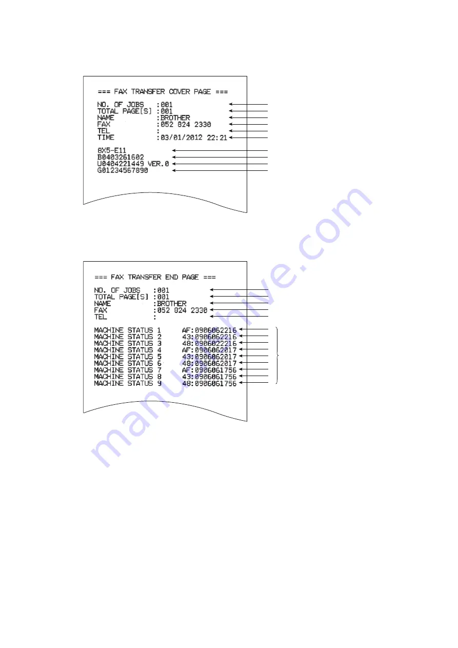
Cover page sample

Fig. 5-8

End page sample

Fig. 5-9

Job number to identify the transmission
Total number of pages to be transferred
Station ID registered in the sender machine
Fax number of the sender machine
Telephone number of the sender machine
Transfer date and time

Model code
Boot ROM information
ROM information
Serial number

Job number to identify the transmission
Total number of pages to be transferred
Station ID registered in the sender machine
Fax number of the sender machine
Telephone number of the sender machine

Error codes

Содержание FAX-2950

Страница 1: ...ERVICE MANUAL MODEL FAX 2840 2845 2890 FAX 2940 2950 2990 MFC 7240 7290 Read this manual thoroughly before maintenance work Keep this manual in a convenient place for quick and easy reference at all times April 2012 SM FAX133 8X5E03 1 ...

Страница 2: ...thout permission in writing from the publisher All other product and company names mentioned in this manual are trademarks or registered trademarks of their respective holders Specifications are subject to change without notice Model FAX 2840 FAX 2845 FAX 2890 FAX 2940 LCD Back Light Handset N A for EU models N A for EU models Scanner Function Model FAX 2950 FAX 2990 MFC 7240 MFC 7290 LCD Back Lig...

Страница 3: ...c Wi Fi WPA WPA2 Wi Fi Protected Access and Wi Fi Protected Setup are either trademarks or registered trademarks of Wi Fi Alliance in the United States and or other countries Intel and Pentium are trademarks of Intel Corporation in the U S and other countries AMD is a trademark of Advanced Micro Devices Inc FaceFilter Studio is a trademark of Reallusion Inc BRAdmin Professional is a trademark of B...

Страница 4: ... 10 1 8 FAX 1 11 1 9 Copy 1 12 1 10 Scanner 1 13 1 11 USB Direct Interface 1 13 CHAPTER 2 TROUBLESHOOTING 1 INTRODUCTION 2 1 1 1 Precautions 2 1 1 2 Initial Check 2 3 2 OVERVIEW 2 5 2 1 Cross section Drawing 2 5 2 1 1 Printer part 2 5 2 1 2 Scanning part 2 6 2 2 Paper Feeding 2 7 2 2 1 Printer part 2 7 2 2 2 Scanning part 2 8 2 3 Operation of Each Part 2 9 2 4 Block Diagram 2 10 2 5 Main Component...

Страница 5: ...anning Image Defect Troubleshooting 2 78 3 9 1 Image defect examples 2 78 3 9 2 Troubleshooting according to scanning image defect 2 78 3 10 Control Panel Troubleshooting 2 81 3 10 1 Nothing is displayed on the LCD 2 81 3 10 2 The control panel does not work 2 81 3 10 3 Lamp malfunction 2 81 3 11 Troubleshooting of FAX Telephone Problems 2 82 3 11 1 FAX cannot be sent 2 82 3 11 2 FAX cannot be rec...

Страница 6: ...Y Hook actuator 3 38 9 14 Unfold support flap 3 38 9 15 Control panel cover link 3 38 9 16 Document chute ASSY 3 39 9 17 Document chute upper ASSY 3 41 9 18 Separation pad ASSY 3 42 9 19 Control panel ASSY 3 43 9 20 Document separate roller 3 45 9 21 ADF motor 3 47 9 22 CIS unit 3 48 9 23 Control panel cover sensor 3 49 9 24 Modem PCB ASSY 3 50 9 25 Inner chute cover 3 51 9 26 Inner chute ASSY 3 5...

Страница 7: ...F YOU REPLACE THE LASER UNIT 4 6 2 1 Entering the Adjusted Value of the Laser Unit 4 6 3 IF YOU REPLACE THE LOW VOLTAGE POWER SUPPLY PCB ASSY 4 8 3 1 Reset of Irregular Power Supply Detection Counter 4 8 4 IF YOU REPLACE THE CIS UNIT 4 9 4 1 Acquisition of White Level Data Function Code 55 4 9 4 2 Scanning and Printing Check 4 9 4 3 Scanning Lock Function Code 06 4 9 5 IF YOU REPLACE THE PANEL UNI...

Страница 8: ...nning position adjustment Function code 57 5 27 1 3 18 Continuous print test Function code 67 5 28 1 3 19 Setting by country Function code 74 5 29 1 3 20 Printout of maintenance information Function code 77 5 32 1 3 21 Operational check of fan Function code 78 5 34 1 3 22 Display of machine log history Function code 80 5 35 1 3 23 Error code indication Function code 82 5 38 1 3 24 Sending communic...

Страница 9: ...claration of Conformity DoC is available on our Website Please go to http solutions brother com choose region eg Europe choose country choose your model choose Manuals choose Declaration of Conformity Select Language when required IEC60825 1 2007 Specification For 220 240V models only This product is a Class 1 laser product as defined in IEC60825 1 2007 specifications The label shown below is atta...

Страница 10: ... use a plug that does not have a cover If in any doubt call a qualified electrician Warning This product must be earthed The wires in the mains lead are coloured in line with the following code Green and Yellow Earth Blue Neutral Brown Live Radio Interference This product complies with EN55022 CISPR Publication 22 Class B EU Directive 2002 96 EC and EN50419 This equipment is marked with the above ...

Страница 11: ...ct identifier that has the format US AAAEQ TXXXX The digits represented by are the REN without a decimal point e g 06 is a REN of 0 6 For earlier products the REN is separately shown on the label If this equipment causes harm to the telephone network the telephone company will notify you in advance that temporary discontinuance of service may be required But if advance notice is not practical the ...

Страница 12: ...tion This equipment generates uses and can radiate radio frequency energy and if not installed and used in accordance with the instructions may cause harmful interference to radio communications However there is no guarantee that interference will not occur in a particular installation If this equipment does cause harmful interference to radio or television reception which can be determined by tur...

Страница 13: ...e Ringer Equivalence Number is an indication of the maximum number of devices allowed to be connected to a telephone interface The termination on an interface may consist of any combination of devices subject only to the requirement that the sum of the RENs of all the devices does not exceed five L indice d équivalence de la sonnerie IES sert à indiquer le nombre maximal de terminaux qui peuvent ê...

Страница 14: ...reign countries Using USA or Canada models overseas is at your own risk and may void your warranty International ENERGY STAR Qualification Statement The purpose of the International ENERGY STAR Program is to promote the development and popularization of energy efficient office equipment As an ENERGY STAR Partner Brother Industries Ltd has determined that this product meets the ENERGY STAR specific...

Страница 15: ...es IMPORTANT IMPORTANT indicates a potentially hazardous situation which if not avoided may result in damage to property or loss of product functionality Prohibition icons indicate actions that must not be performed Electrical Hazard icons alert you to possible electrical shock Fire Hazard icons alert you to the possibility of fire Hot Surface icons warn you not to touch product parts that are hot...

Страница 16: ...oduct including for routine maintenance such as cleaning make sure you have unplugged the power cord from the AC power outlet as well as Ethernet RJ 45 cables Network models only from the product Never push objects of any kind into this product through cabinet slots since they may touch dangerous voltage points or short out parts DO NOT handle the plug with wet hands DO NOT use this product during...

Страница 17: ...make sure that the total of all products plugged into the AC power outlet does not exceed 15 amperes DO NOT plug one extension cord into another DO NOT put a toner cartridge or a toner cartridge and drum unit assembly into a fire It could explode resulting in injuries DO NOT use flammable substances any type of spray or an organic solvent liquid containing alcohol or ammonia to clean the inside or...

Страница 18: ...m do not try to open the enclosure of the laser unit ACHTUNG Im Falle von Störungen der Lasereinheit muß diese ersetzt werden Das Gehäuse der Lasereinheit darf nicht geöffnet werden da sonst Laserstrahlen austreten können HOT SURFACE After you have just used the product some internal parts of the product will be extremely hot Wait at least 10 minutes for the product to cool down before you touch t...

Страница 19: ...rewdriver or other reflective object in the path of the laser beam Be sure to take off any personal accessories such as watches and rings before working on the machine A reflected beam though invisible can permanently damage the eyes Since the beam is invisible the following caution label is attached on the laser unit ...

Страница 20: ...Confidential CHAPTER 1 SPECIFICATIONS ...

Страница 21: ...FICATIONS LIST 1 1 1 1 General 1 1 1 2 Network Connectivity 1 6 1 3 Service Information 1 6 1 4 Supplies 1 7 1 5 Paper 1 9 1 5 1 Paper handling 1 9 1 5 2 Media specifications 1 9 1 6 Printable Scannable Area 1 10 1 7 Telephone 1 10 1 8 FAX 1 11 1 9 Copy 1 12 1 10 Scanner 1 13 1 11 USB Direct Interface 1 13 ...

Страница 22: ...an 10 0 seconds for U S A N A for Europe N A Less than 8 5 seconds for U S A China Less than 10 0 seconds for Europe From Sleep mode Less than 19 0 seconds for U S A N A for Europe N A Less than 16 5 for U S A China Less than 19 0 seconds for Europe CPU ARM9 200 MHz Memory Standard 16 MB Option N A Interface USB Hi Speed 2 0 FAX 2840 2845 for Europe N A Power consumption Peak 1080 W Copying Averag...

Страница 23: ... to 80 without condensation Storage 10 to 90 without condensation Dimensions W x D x H Carton Size 458 x 476 x 436 mm 180 x 187 x 172 inch Machine Size 360 x 368 x 311 mm 145 x 142 x 122 inch Weights Without Carton With toner drum 9 0 kg 19 8 lb FAX 2840 2940 for Europe 8 8 kg 19 4 lb LCD Size 1 85 x 0 43 inch 16 characters x 2 lines For China 1 89 x 0 39 inch 10 characters x 2 lines Specification...

Страница 24: ...leep mode Less than 16 5 seconds Less than 19 0 seconds Less than 16 5 seconds CPU ARM9 200 MHz Memory Standard 16 MB Option N A Interface USB Hi Speed 2 0 Power consumption Peak 1080 W Copying Average Approximately 420 W except for China Average Approximately 445 W for China Quiet Mode Copying N A Ready Average Approximately 55 W Sleep Wireless LAN ON N A Deep Sleep Average Approximately 1 5 W Au...

Страница 25: ...ne Size 360 x 368 x 311 mm 145 x 142 x 122 inch Weights Without Carton With toner drum 9 0 kg 19 8 lb LCD Size 1 85 x 0 43 inch 16 characters x 2 lines For China 1 89 x 0 39 inch 10 characters x 2 lines Specifications are subject to change without notice Model FAX 2950 FAX 2990 MFC 7240 MFC 7290 ...

Страница 26: ... Intel 64 or AMD 64 supported CPU 512 MB 1 GB 500 MB 1 2 GB Windows 7 1 4 Intel Pentium 4 or equivalent 64 bit Intel 64 or AMD 64 supported CPU 1 GB 32 bit 2 GB 64 bit 1 GB 32 bit 2 GB 64 bit 650 MB Macintosh Operating System OS X 10 5 8 PowerPC G4 G5 Intel Processor 512 MB 1 GB 80 MB 400 MB Printing PC Fax Send 3 Scanning USB OS X 10 6 x Intel Processor 1 GB 2 GB OS X 10 7 x Intel Processor 2 GB ...

Страница 27: ...mmunication mode N A Network security N A Specifications are subject to change without notice Part Approximate Life pages Machine life 50 000 pages A4 Letter size or 5 years MTBF 4 000 hours MTTR 0 5 hours Maximum monthly volume Up to 10 000 pages Periodical maintenance parts Fuser Unit 50 000 pages Laser Unit 50 000 pages PF kit 50 000 pages Specifications are subject to change without notice ...

Страница 28: ...thout opening 6 months after opening Drum unit Life expectancy Approximately 12 000 pages 1 page job The life expectancy varies according to the use condition Shelf life 2 years The self life of toner cartridge and drum unit is guaranteed under the normal condition as below Temperature Normal condition 0 to 40 C Storage condition at the temperature of 40 to 50 C Up to 5 days Storage condition at t...

Страница 29: ...ly 12 000 pages 1 page job The life expectancy varies according to the use condition Shelf life 2 years The self life of toner cartridge and drum unit is guaranteed under the normal condition as below Temperature Normal condition 0 to 40 C Storage condition at the temperature of 40 to 50 C Up to 5 days Storage condition at the temperature of 20 to 0 C Up to 5 days Humidity Normal condition 35 to 8...

Страница 30: ...k Paper Recycled Paper Bond Paper Labels and Envelopes Duplex N A ADF Plain Paper Recycled Paper Paper weight Paper tray 1 60 to 105 g m2 16 to 28 lb Manual feed slot 60 to 163 g m2 16 to 43 lb Duplex N A ADF 64 to 90 g m2 17 to 24 lb Paper size Paper tray 1 A4 Letter B5 ISO JIS A5 A5 Long Edge B6 ISO A6 Executive Legal 1 Folio Except for EU OCE CHN Manual feed slot Width 76 2 to 216 mm Length 116...

Страница 31: ... A4 3 mm 0 12 inch 1 mm 0 4 inch Copy Letter 3 mm 0 12 inch 4 mm 0 16 inch Legal 3 mm 0 12 inch 4 mm 0 16 inch A4 3 mm 0 12 inch 3 mm 0 12 inch Scan 1 Letter 3 mm 0 12 inch 3 mm 0 12 inch Legal 3 mm 0 12 inch 3 mm 0 12 inch A4 3 mm 0 12 inch 3 mm 0 12 inch Print 1 Letter 4 mm 0 16 inch 4 mm 0 16 inch Legal 4 mm 0 16 inch 4 mm 0 16 inch A4 4 mm 0 16 inch 4 mm 0 16 inch 1 For MFC 7240 7290 FAX 2950 ...

Страница 32: ...Super G3 Color FAX Sending N A Receiving N A Internet FAX N A Specifications are subject to change without notice Model FAX 2950 FAX 2990 MFC 7240 MFC 7290 Modem Speed 33 600 bps FAX 14 400 bps FAX 33 600 bps FAX Transmission speed Approximately 2 5 seconds ITU T Test Chart 1 Std resolution JBIG Approximately 7 0 seconds ITU T Test Chart 1 Std resolution MMR Approximately 2 5 seconds ITU T Test Ch...

Страница 33: ...r U S A and China Less than 29 seconds for Europe Resolution dpi 300 x 600 dpi Auto duplex scanning copy N A Specifications are subject to change without notice Model FAX 2950 FAX 2990 MFC 7240 MFC 7290 Copy Speed A4 Letter Up to 24 24 ppm Up to 20 21 ppm Up to 24 24 ppm First copy out time From Ready mode and Paper tray Less than 11 seconds Less than 12 seconds Less than 11 seconds From Sleep mod...

Страница 34: ...n scanning x 600 sub scanning dpi Resolution Interpolated Maximum scanning 19200 main scanning x 19200 sub scanning dpi Scanning speed Monochrome A4 2 63 seconds Letter 2 47 seconds Color N A Specifications are subject to change without notice Model All Models PictBridge N A Direct print N A Specifications are subject to change without notice ...

Страница 35: ...Confidential CHAPTER 2 TROUBLESHOOTING ...

Страница 36: ... section Drawing 2 5 2 1 1 Printer part 2 5 2 1 2 Scanning part 2 6 2 2 Paper Feeding 2 7 2 2 1 Printer part 2 7 2 2 2 Scanning part 2 8 2 3 Operation of Each Part 2 9 2 4 Block Diagram 2 10 2 5 Main Components 2 11 2 6 Life of Toner Cartridge and Drum Unit 2 12 3 ERROR INDICATIONS 2 14 3 1 Error Codes 2 14 3 2 Error Messages 2 19 3 3 Communication Error Codes 2 21 3 4 Error Cause and Remedy 2 24 ...

Страница 37: ... Nothing is displayed on the LCD 2 81 3 10 2 The control panel does not work 2 81 3 10 3 Lamp malfunction 2 81 3 11 Troubleshooting of FAX Telephone Problems 2 82 3 11 1 FAX cannot be sent 2 82 3 11 2 FAX cannot be received 2 82 3 11 3 Communication error occurs 2 82 3 11 4 Caller ID is not displayed 2 82 3 11 5 Cannot talk on the handset 2 83 3 12 Other Troubleshooting 2 84 3 12 1 The machine is ...

Страница 38: ... make sure that you hold the connector body and not the cables 3 Static electricity charged in your body may damage electronic parts Before handling the PCBs touch a metal portion of the machine to discharge static electricity charged in your body When transporting PCBs be sure to wrap them in conductive sheets When replacing the PCBs put on a grounding wrist band and perform the job on a conducti...

Страница 39: ... Verify again that the repaired portion works properly WARNING DO NOT use any flammable spray or flammable solvent such as alcohol benzine or thinner in or around the machine Otherwise a fire or electric shock may result ...

Страница 40: ...NOT carry the machine by holding it at the bottom 5 The machine should be installed 10 cm or more from a wall or other objects to avoid the ventilation port of the fan being blocked Power supply 1 Power described on the rating label attached on the machine is supplied Power fluctuation should be within 10 of the rated voltage 2 The AC input power supply is within the regulated value 3 The cables a...

Страница 41: ... on the plate and separation pad may cause paper feed problems If condensation has occurred leave the machine for at least two hours to allow it to reach room temperature If the drum unit is unpacked soon after it is moved from a cold place to a warm room condensation may occur inside the drum unit which may cause incorrect images Instruct the user to allow the drum unit to come to room temperatur...

Страница 42: ...roller Exposure drum Developer roller Supply roller Laser unit Registration rear actuator Manual feed slot cover Registration front actuator Registration roller Paper tray Separation pad Separation roller Plate Pick up roller Transfer roller Halogen heater Pressure roller Heat roller Eject roller 1 Back cover Paper eject actuator ...

Страница 43: ...ng part Fig 2 2 ADF document output support flap Document feed roller Document separate roller Document tray ASSY Document ejection roller Document scanning position actuator Document detection actuator Separation pad ASSY CIS unit ...

Страница 44: ...2 7 Confidential 2 2 Paper Feeding 2 2 1 Printer part Fig 2 3 Rear paper eject path Back side Front side Manual feed slot path Paper tray path ...

Страница 45: ...2 8 Confidential 2 2 2 Scanning part Fig 2 4 ...

Страница 46: ...oller Transfer the toner adhered to the exposure drum to the paper by applying a minus charge and feed the paper to the fuser unit Heat roller pressure roller Fuse the toner transferred to the paper by heat and pressure and feed the paper to the eject roller 1 Paper eject actuator Detect whether or not the paper is ejected from the fuser unit Eject roller 1 Feed the paper ejected from the fuser un...

Страница 47: ...switch Low voltage power supply PCB ASSY Registration clutch ASSY T1 clutch ASSY Internal temperature thermistor Control panel cover sensor ADF motor Main motor Front cover sensor LCD handset models only Panel PCB ASSY Document scanning position sensor New toner sensor PCB ASSY Halogen heater Laser unit Fuser unit Registration front rear sensor PCB ASSY LD PCB BD sensor Polygon motor Modem PCB ASS...

Страница 48: ...ort flap Side cover R Modem PCB ASSY Handset holder Hook actuator Hook switch PCB ASSY Eject pinch roller R ASSY Eject pinch roller L ASSY Inner chute ASSY Fuser unit cover Fuser unit Back cover Outer chute ASSY Main PCB ASSY Side cover L Internal temperature thermistor New toner sensor PCB ASSY Paper tray Front cover ASSY Low voltage power supply PCB ASSY High voltage power supply PCB ASSY Main f...

Страница 49: ...eloper roller also rotates for the warm up operation when the power is turned ON and when the cover is opened or closed Therefore when these operations are frequently performed the life of toner cartridges is shortened The table below shows the worst case in which the warm up operation is performed when the power is turned ON The life in Continue Mode is shown below However print may become blur o...

Страница 50: ...ife Drum rotations are required for the warm up operation when the power is turned ON or when the cover is opened or closed Therefore when these operations are frequently performed the life of drum unit is shortened The table below shows the worst case in which the warm up operation is performed when the power is turned ON The numeral values provided on this page are current as of April 2012 These...

Страница 51: ...tified error occurred 2 27 1B An unidentified error occurred 2 25 3A An unidentified error occurred 2 27 1C An unidentified error occurred 2 25 3B An error occurred during access to the DRAM in the main PCB 2 27 1D An unidentified error occurred 2 25 3C An unidentified error occurred 2 27 1E The drum unit will reach the end of life soon 2 25 3D An unidentified error occurred 2 27 1F An unidentifie...

Страница 52: ...red 2 33 59 Rechecking the error after the power switch was turned OFF and then ON again because an error was detected by the center thermistor of the fuser unit 2 30 6F The center thermistor or the side thermistor of the fuser unit detected a temperature error 2 34 5A An unidentified error occurred 2 31 70 An unidentified error occurred 2 34 5B An unidentified error occurred 2 31 71 Detected an e...

Страница 53: ...2 87 An unidentified error occurred 2 40 9A The registration front sensor detected that there was no paper set in the manual feed slot when feeding from the manual feed slot was set 2 43 88 The eject sensor does not detect paper pass after the registration rear sensor detected the end of paper pass 2 40 9B The number of rotations of the developer roller reached the upper limit when Continue Mode i...

Страница 54: ...occurred 2 52 AD Image processing cannot be completed correctly because the number of pixels required for image processing is insufficient in the scanned data 2 49 C6 An unidentified error occurred 2 52 AE An unidentified error occurred 2 49 C7 There is insufficient memory to expand PC print data 2 53 AF An unidentified error occurred 2 49 C8 An unidentified error occurred 2 53 B0 Detected that th...

Страница 55: ...wer than the specified temperature 2 55 F3 An unidentified error occurred 2 59 DF An unidentified error occurred 2 55 F4 An unidentified error occurred 2 59 E0 An error occurred in the ROM check sum 2 55 F5 An unidentified error occurred 2 59 E1 Software bug 2 56 F6 An unidentified error occurred 2 59 E2 When the center thermistor of the fuser unit is higher than the idle temperature the side ther...

Страница 56: ...the document length was 90 cm or more while scanning the document A2 2 46 The document scanning position sensor does not detect the leading edge of the document although the document has been fed for the specified distance A3 2 47 Drum End Soon The drum unit will reach the end of life soon 1E 2 25 Drum Error Detected discharge that may be attributable to dirty corona wire on the drum unit 7D 2 37 ...

Страница 57: ...r limit when Stop Mode is set for the toner cartridge 63 2 31 The number of rotations of the developer roller will reach the upper limit soon when Continue Mode is set for the toner cartridge 9C 2 44 Scan Unable Refer to the error code for details indicates the error code Scanner Error Error related to the scanner unit Check the error code to check the details B0 to BD 2 49 to 2 51 Self Diagnostic...

Страница 58: ...ed 2 82 20 06 CRC error in answerback 2 82 20 07 Echo command received 2 82 20 08 Invalid command received 2 82 20 09 Command ignored once for document setting or for damping out at turn around transmission 2 82 20 0A T5 time out error 2 82 20 0B CRP received 2 82 20 0C EOR or NULL received 2 82 20 0D Corresponding command not received although the FIF command sending bit is ON 2 82 20 0E EOR comm...

Страница 59: ... A0 15 Time out 13 seconds or more for one line transmission 2 82 A0 16 RTC not found or carrier OFF detected for 6 seconds 2 82 A0 17 RTC found but no command detected for 60 seconds or more 2 82 A0 19 No video data to be sent 2 82 A8 01 RTN PIN or ERR received sending terminal 2 82 A9 01 RTN PIN or ERR sent receiving terminal 2 82 AA 18 Receive buffer full during receiving into memory 2 82 B0 01...

Страница 60: ... 3 1 Error Codes in this chapter 2 82 Establishment of FAX communication FAX communication is established when the calling station receives a DIS reception capability signal from the called station and the called station receives a NSS or DCS communications test signal from the calling station Code 1 Code 2 Cause Refer to ...

Страница 61: ...nd the installation site fluctuation of the power supply voltage and failures in the software An unidentified error occurred Error code 19 The drum reached the end of life while the WSW 78 selector 1 was set to ON User Check Turn OFF the power switch and turn it ON again after a while Step Cause Remedy 1 Main PCB failure Replace the main PCB ASSY User Check Turn OFF the power switch and turn it ON...

Страница 62: ...ur in the normal use The conceivable causes are noise around the installation site fluctuation of the power supply voltage and failures in the software An unidentified error occurred User Check Turn OFF the power switch and turn it ON again after a while Step Cause Remedy 1 Main PCB failure Replace the main PCB ASSY Drum End Soon User Check Prepare a new drum unit Step Cause Remedy 1 Main PCB fail...

Страница 63: ... failure of the internal temperature thermistor harness Reconnect the internal temperature thermistor harness 2 Internal temperature thermistor failure Replace the internal temperature thermistor 3 Main PCB failure Replace the main PCB ASSY User Check Turn OFF the power switch and turn it ON again after a while Step Cause Remedy 1 Main PCB failure Replace the main PCB ASSY Print Unable 36 Turn the...

Страница 64: ...occur in the normal use The conceivable causes are noise around the installation site fluctuation of the power supply voltage and failures in the software An unidentified error occurred User Check Turn OFF the power switch and turn it ON again after a while Step Cause Remedy 1 Main PCB failure Replace the main PCB ASSY Print Unable 3B Turn the power off and then back on again Step Cause Remedy 1 M...

Страница 65: ...en the Front Cover then install the Toner Cartridge User Check Install the toner cartridge Step Cause Remedy 1 Connection failure of the new toner sensor harness Reconnect the new toner sensor harness 2 New toner sensor failure Check the sensor performance following the procedure in Function code 32 If any problem occurs replace the new toner sensor PCB ASSY 3 Main PCB failure Replace the main PCB...

Страница 66: ... error occurred User Check Turn OFF the power switch and turn it ON again after a while Step Cause Remedy 1 Main PCB failure Replace the main PCB ASSY Cover is Open Close the Fuser Cover which can be found behind the Back Cover of the machine User Check Close the fuser unit cover properly Step Cause Remedy 1 Paper eject actuator catching on some position Correct the position of the paper eject act...

Страница 67: ...e error code that has reoccurred Self Diagnostic Will Automatically Restart within 15 minutes Step Cause Remedy 1 Connection failure of the center thermistor harness of the fuser unit Reconnect the center thermistor harness of the fuser unit 2 Connection failure of the heater harness of the fuser unit Reconnect the heater harness of the fuser unit 3 Connection failure of the eject sensor PCB harne...

Страница 68: ...rred User Check Turn OFF the power switch and turn it ON again after a while Step Cause Remedy 1 Main PCB failure Replace the main PCB ASSY Replace Toner Open the Front Cover replace Toner Cartridge User Check Replace the toner cartridge with a new one Press the Menu button Next press the 1 button and 7 button to clear the Stop Mode and shift to the Continue Mode Step Cause Remedy 1 Main PCB failu...

Страница 69: ...onceivable causes are noise around the installation site fluctuation of the power supply voltage and failures in the software An unidentified error occurred Toner Low Prepare New Toner Cartridge User Check Prepare a new toner cartridge Step Cause Remedy 1 Main PCB failure Replace the main PCB ASSY User Check Turn OFF the power switch and turn it ON again after a while Step Cause Remedy 1 Main PCB ...

Страница 70: ...d the installation site fluctuation of the power supply voltage and failures in the software An unidentified error occurred Print Unable 6A Turn the power off and then back on again Print Unable 6B Turn the power off and then back on again Print Unable 6C Turn the power off and then back on again Print Unable 6D Turn the power off and then back on again Step Cause Remedy 1 Connection failure of th...

Страница 71: ...rror occurred Print Unable 6F Turn the power off and then back on again Step Cause Remedy 1 Connection failure of the fuser unit harness Reconnect the fuser unit harness 2 Fuser unit failure Replace the fuser unit 3 Low voltage power supply PCB failure Replace the low voltage power supply PCB ASSY 4 Eject sensor PCB failure Replace the eject sensor PCB ASSY 5 Main PCB failure Replace the main PCB ...

Страница 72: ...ack on again Print Unable 72 Turn the power off and then back on again User Check There is a possibility that the condensation has occurred Turn OFF the power and leave the machine at least one hour in a well ventilated place And then turn ON the power Step Cause Remedy 1 Correction value error of the laser unit Enter the correction value of the laser unit correctly 2 Connection failure of the las...

Страница 73: ... Cause Remedy 1 Internal temperature thermistor failure Replace the internal temperature thermistor 2 Main PCB failure Replace the main PCB ASSY Print Unable 76 Turn the power off and then back on again Print Unable 78 Turn the power off and then back on again Step Cause Remedy 1 Fuser unit failure Replace the fuser unit 2 Low voltage power supply PCB failure Replace the low voltage power supply P...

Страница 74: ... User Check Turn OFF the power switch and turn it ON again after a while Step Cause Remedy 1 Main PCB failure Replace the main PCB ASSY Drum Error Open the Front Cover and slide the blue tab across the Drum Unit several times User Check Clean the corona wire of the drum unit Turn OFF the power switch and turn it ON again after a while Step Cause Remedy 1 Dirt on electrodes of the drum unit and tho...

Страница 75: ...supply voltage and failures in the software An unidentified error occurred Size mismatch Fax received Set correct paper size in menu User Check Reset the paper size setting in menu Step Cause Remedy 1 Main PCB failure Replace the main PCB ASSY Size mismatch Reload correct paper then press Start User Check Set the A4 size paper Step Cause Remedy 1 Registration front sensor failure Replace the regis...

Страница 76: ...Reset Function Drum in Chapter 5 Step Cause Remedy 1 Main PCB failure Replace the main PCB ASSY Jam Rear Open the Back Cover and remove the jammed paper then press Start User Check Check that the paper is not jammed If jammed remove it Step Cause Remedy 1 Foreign object in the feed system at the rear section of the machine Remove the foreign object in the feed system at the rear section of the mac...

Страница 77: ...d User Check Turn OFF the power switch and turn it ON again after a while Step Cause Remedy 1 Main PCB failure Replace the main PCB ASSY Jam Inside Open the Front Cover pull out the Drum Unit completely and remove the jammed paper User Check Check that the paper is not jammed If jammed remove it Step Cause Remedy 1 Connection failure of the eject sensor PCB ASSY harness Reconnect the eject sensor ...

Страница 78: ...hat the thickness of the paper is 60 to 105 g m2 Check that there is not too much paper set in the tray Step Cause Remedy 1 Coming off of the registration front actuator Reattach the registration front actuator 2 Connection failure of the registration front rear sensor PCB ASSY harness Reconnect the registration front rear sensor PCB ASSY harness 3 Registration front rear sensor PCB failure Check ...

Страница 79: ...ied error occurred Cover is Open Make sure there is no paper jammed inside the machine and close the Back Cover then press Start User Check Close the fuser unit cover Remove the jammed paper around the back cover Step Cause Remedy 1 Paper eject actuator catching on some position Correct the position of the paper eject actuator 2 Eject sensor PCB failure Replace the eject sensor PCB ASSY 3 Main PCB...

Страница 80: ... manual feed slot Step Cause Remedy 1 Connection failure of the registration front rear sensor PCB ASSY harness Reconnect the registration front rear sensor PCB ASSY harness 2 Main PCB failure Replace the main PCB ASSY 3 Registration front sensor failure Check the performance of the registration front sensor following the procedure in Function code 32 If any problem occurs replace the regist frame...

Страница 81: ...tridge is replaced or the memory is full User Check Replace the toner cartridge with a new one Step Cause Remedy 1 New toner actuator catching on some position when the error message does not disappear Correct the position of the new toner actuator 2 Connection failure of the new toner sensor harness when the error message does not disappear Reconnect the new toner sensor harness 3 New toner senso...

Страница 82: ...y Step Cause Remedy 1 Registration front actuator catching on some position Correct the position of the registration front actuator 2 Connection failure of the registration front rear sensor PCB ASSY harness Reconnect the registration front rear sensor PCB ASSY harness 3 Registration front rear sensor PCB failure Replace the regist frame ASSY 4 Low voltage power supply PCB failure Replace the low ...

Страница 83: ...ront cover sensor is broken which is provided at inside of front cover Replace the front cover ASSY 3 Front cover sensor failure Check the performance of the front cover sensor following the procedure in Function code 32 If any problem occurs replace the high voltage power supply PCB ASSY 4 Main PCB failure Replace the main PCB ASSY Document Jam Clear the scanner jam then press the Stop Key User C...

Страница 84: ... 2 Connection failure of the document scanning position sensor harness Reconnect the document scanning position sensor harness 3 Document scanning position sensor failure Replace the panel PCB ASSY 4 Main PCB failure Replace the main PCB ASSY Cover is Open Close the Control Panel Cover User Check Close the control panel cover Step Cause Remedy 1 Coming off of the control panel cover sensor Reattac...

Страница 85: ...nable Remove the original document Turn the power off then on again Scan Unable A6 See Troubleshooting and routine maintenance chapter in User s Guide User Check Turn OFF the power switch and turn it ON again after a while Step Cause Remedy 1 Incorrect white level data Execute Function code 55 2 CIS unit failure Replace the CIS unit 3 Main PCB failure Replace the main PCB ASSY Print Unable A7 Turn...

Страница 86: ...oltage and failures in the software An unidentified error occurred Error code B0 Detected that the CIS harness was not inserted correctly User Check Turn OFF the power switch and turn it ON again after a while Step Cause Remedy 1 Main PCB failure Replace the main PCB ASSY Scan Unable Remove the original document Turn the power off then on again Step Cause Remedy 1 CIS unit failure Replace the CIS ...

Страница 87: ...ed error occurred Error code B7 The voltage value was above the upper limit during scanning Error code B8 The voltage value was below the lower limit during scanning Error code B9 The white level does not increase during scanning although the light intensity was increased Scanner Error Scanner Error Step Cause Remedy 1 CIS unit failure Replace the CIS unit 2 Main PCB failure Replace the main PCB A...

Страница 88: ... and failures in the software An unidentified error occurred Error code BD A black level not within the standard was scanned when function code 55 was executed User Check Turn OFF the power switch and turn it ON again after a while Step Cause Remedy 1 Main PCB failure Replace the main PCB ASSY Scanner Error Step Cause Remedy 1 Dirt on the pressure bar Clean the pressure bar 2 CIS unit failure Repl...

Страница 89: ...ower supply voltage and failures in the software An unidentified error occurred User Check Turn OFF the power switch and turn it ON again after a while Step Cause Remedy 1 Main PCB failure Replace the main PCB ASSY Scanner Error User Check Install a new toner cartridge Step Cause Remedy 1 Coming off of the new toner actuator Reattach the new toner actuator 2 Connection failure of the new toner sen...

Страница 90: ...d while initializing the modem Out of Memory Press Stop key User Check Turn OFF the power switch and turn it ON again after a while Step Cause Remedy 1 Main PCB failure Replace the main PCB ASSY User Check Turn OFF the power switch and turn it ON again after a while Step Cause Remedy 1 Main PCB failure Replace the main PCB ASSY Print Unable D1 See Troubleshooting and routine maintenance chapter in...

Страница 91: ...n PCB failure Replace the main PCB ASSY Print Unable DD See Troubleshooting and routine maintenance chapter in User s Guide User Check Turn OFF the power switch and turn it ON again after a while Step Cause Remedy 1 Connection failure of the fuser unit harnesses Reconnect the fuser unit harnesses 2 Connection failure of the eject sensor PCB harness Reconnect the eject sensor PCB harness 3 Eject se...

Страница 92: ... and turn it ON again after a while Step Cause Remedy 1 Connection failure of the center thermistor or side thermistor harness of the fuser unit Reconnect the center thermistor or side thermistor harness 2 Side thermistor or center thermistor failure Replace the fuser unit 3 Eject sensor PCB failure Replace the eject sensor PCB ASSY 4 Main PCB failure Replace the main PCB ASSY User Check Turn OFF ...

Страница 93: ...en back on again User Check Turn OFF the power switch and turn it ON again after a while Step Cause Remedy 1 Main PCB failure Replace the main PCB ASSY Print Unable E2 Turn the power off and then back on again User Check Turn OFF the power switch and turn it ON again after a while Step Cause Remedy 1 Connection failure of the center thermistor or side thermistor harness of the fuser unit Reconnect...

Страница 94: ...dy 1 Main PCB failure Replace the main PCB ASSY User Check Turn OFF the power switch and turn it ON again after a while Step Cause Remedy 1 Main PCB failure Replace the main PCB ASSY Print Unable EC Turn the power off and then back on again User Check Turn OFF the power switch and turn it ON again after a while Step Cause Remedy 1 Connection failure of the main fan harness Reconnect the main fan h...

Страница 95: ...e low voltage power supply PCB ASSY Reset the irregular power supply detection counter following the procedure described in 3 IF YOU REPLACE THE LOW VOLTAGE POWER SUPPLY PCB ASSY in Chapter 4 2 Main PCB failure Replace the main PCB ASSY CAUTION The irregular power supply detection error error code EF occurs when there is a large distortion in the power supply voltage supplied to the machine In thi...

Страница 96: ... the installation site fluctuation of the power supply voltage and failures in the software An unidentified error occurred User Check Turn OFF the power switch and turn it ON again after a while Step Cause Remedy 1 Main PCB failure Replace the main PCB ASSY Machine Error F9 Step Cause Remedy 1 Power turned OFF while the function code 74 is being executed and PARAMETER INIT is being displayed Re en...

Страница 97: ... Check Check that the paper tray is loaded correctly Check that the paper is loaded into the paper tray correctly Check that the paper smaller than the specified size is not loaded Adjust the paper guide corresponding to the position of paper guide Check that there is not too much paper set in the tray Clean the surface of the separation pad or pick up separate roller Step Cause Remedy 1 Attachmen...

Страница 98: ...ation environment is appropriate and the corona wire cleaning lever is at the specified position Step Cause Remedy 1 Fuser unit dirty Clean the entrance of the fuser unit or clean the pressure roller 2 Paper eject roller dirty Clean the eject roller User Check Check that the paper is loaded into the paper tray correctly Adjust the paper guide corresponding to the paper size Check that there is not...

Страница 99: ...hickness of the paper is 60 to 105 g m2 Turn over the stack of paper in the paper tray or try rotating the paper 180 degrees in the paper tray Turn the green envelope levers in the direction of the black arrow Refer to Fig 2 7 Step Cause Remedy 1 Foreign object inside the fuser unit Remove the foreign object inside the fuser unit 2 Fuser unit failure Replace the fuser unit ...

Страница 100: ...per Fig 2 8 User Check Choose Reduce Paper Curl mode in the driver Turn the anti curl levers in the direction of the black arrow Refer to Fig 2 8 Step Cause Remedy 1 Fuser unit failure Replace the fuser unit Anti curl lever Anti curl lever ...

Страница 101: ...distortion 2 69 All black 2 69 Dirt on the back of paper 2 69 Vertical streaks 2 70 Black vertical streaks in a light background 2 70 Black horizontal stripes 2 71 White vertical streaks 2 72 White horizontal streaks 2 72 Faint print 2 72 White spots 2 73 Black spots or dirt 2 73 Black band 2 74 Downward fogging of solid color 2 74 Horizontal lines 2 74 Ghost 2 75 Fogging 2 75 ...

Страница 102: ...ity by the Density Adjustment Replace the drum unit with a new one Replace the toner cartridge with a new one Replacing the used toner cartridge with a relatively new used toner cartridge can cause this problem Check that condensation has not formed in the machine or the installation location is appropriate Step Cause Remedy 1 Dirt on electrodes of the drum unit and those of the machine Clean the ...

Страница 103: ... the machine Fig 2 11 How to clean the electrodes Turn OFF the power switch Unplug the power cord from the AC power outlet and leave the machine for a few minutes Then wipe the electrodes above carefully with a dry lint free cloth Be careful not to change the shapes of the electrodes Side view of drum unit ...

Страница 104: ...djustment Clean the corona wire of the drum unit Replace the drum unit with a new one Replace the toner cartridge with a new one Replacing the relatively new toner cartridge with a used toner cartridge can cause this problem If this problem occurs immediately after deep sleep mode is released install the latest firmware If installing the firmware is not possible open and close the front cover and ...

Страница 105: ...e the main PCB ASSY User Check Check the machine s environment High temperature and high humidity or low temperature and low humidity conditions can cause this problem Clean the corona wire of drum unit Replace the drum unit with a new one Replace the toner cartridge with a new one Remove the elastic band from the drum unit Step Cause Remedy 1 Dirt on electrodes of the drum unit and those of the m...

Страница 106: ...he machine Refer to Fig 2 10 and Fig 2 11 2 Connection failure of the scanner harness of the laser unit Reconnect the scanner harness of the laser unit 3 Earth plate connection failure Reconnect the earth plate between the laser unit and develop drive sub ASSY securely and secure the screw 4 High voltage power supply PCB failure Replace the high voltage power supply PCB ASSY 5 Laser unit failure R...

Страница 107: ...s after printing a few pages the adhesive of the label or the like paper powder or dirt may be attached on the surface of the exposure drum Wipe off the dirt on the exposure drum Refer to User s Guide and perform the Drum Cleaning Replace the drum unit with a new one Replace the toner cartridge with a new one The corona wire cleaning lever is not at the home position Step Cause Remedy 1 Dirt in th...

Страница 108: ...Refer to Fig 2 10 and Fig 2 11 2 Bend of tray earth spring 1 Correct bending of the tray earth spring 2 Replace the paper tray 3 Scratch or dirt on the heat roller horizontal stripes at intervals of 53 4 mm Replace the fuser unit 4 High voltage power supply PCB failure Replace the high voltage power supply PCB ASSY 5 Main PCB failure Replace the main PCB ASSY CAUTION Image defects which appear per...

Страница 109: ...medy 1 Laser unit failure Replace the laser unit User Check This problem may disappear after printing several sheets of paper When the machine has not been used for a long time try printing several sheets of paper Replace the drum unit with a new one Replace the toner cartridge with a new one Step Cause Remedy 1 Dirt on electrodes of the drum unit and those of the machine Clean the electrodes of t...

Страница 110: ... failure Replace the main PCB ASSY User Check When the black spots appear at intervals of 32 5 mm replace the toner cartridge with a new one If the same problem occurs after printing a few pages the adhesive of the label or the like paper powder or dirt may be attached on the surface of the exposure drum Wipe off the dirt on the exposure drum Refer to User s Guide and perform the Drum Cleaning Whe...

Страница 111: ...age power supply PCB failure Replace the high voltage power supply PCB ASSY 2 Main PCB failure Replace the main PCB ASSY User Check The paper tray earth spring on the machine side may be dirty Clean it with a dry cloth Replace the drum unit with a new one Replace the toner cartridge with a new one Step Cause Remedy 1 Dirt on electrodes of the drum unit and those of the machine Clean the electrodes...

Страница 112: ...gh voltage power supply PCB ASSY 2 Main PCB failure Replace the main PCB ASSY User Check This problem may disappear after printing approximately 10 pages of completely blank sheets Replace the drum unit with a new one Replace the toner cartridge with a new one Do not use acid paper Step Cause Remedy 1 High voltage power supply PCB failure Replace the high voltage power supply PCB ASSY 2 Main PCB f...

Страница 113: ...x 3 Select the USB at the bottom of Hardware in left side Content 4 Select the MFC XXXX or FAX XXXX in the USB Device Tree 5 Check the Product ID under MFC XXXX or FAX XXXX Product ID hexadecimal FAX 2840 02A3h FAX 2950 02A7h FAX 2845 02A4h MFC 7290 02A8h MFC 7240 02A5h FAX 2890 02AAh FAX 2940 02A6h FAX 2990 02ABh User Check Check that the USB cable or LAN cable is not damaged Check that the corre...

Страница 114: ...or performance following the procedure in Function code 32 If any problem occurs replace the control panel cover sensor 4 Document separation roller failure Replace the document separation roller 5 ADF motor failure Replace the ADF motor 6 Main PCB failure Replace the main PCB ASSY User Check Check that the paper thinner than the specification is not used for the document Flip through the paper an...

Страница 115: ...tting of the contrast does not become light Clean the CIS glass Step Cause Remedy 1 Incorrect white level data Perform the acquisition of white level data Function code 55 2 CIS unit failure Replace the CIS unit 3 Main PCB failure Replace the main PCB ASSY Dark or bluish white 2 79 Light 2 78 Faulty registration 2 79 White vertical streak 2 80 Completely blank 2 80 Vertical streaks 2 80 ...

Страница 116: ...actuator User Check Check that the setting of the contrast does not become dark If this problem occurs immediately after deep sleep mode is released install the latest firmware If installing the firmware is not possible open and close the front cover and then retry printing after the main motor has stopped Step Cause Remedy 1 Incorrect white level data Perform the acquisition of white level data F...

Страница 117: ...ce the CIS unit 2 Main PCB failure Replace the main PCB ASSY User Check Check that the CIS glass is not stained Step Cause Remedy 1 CIS unit failure Replace the CIS unit User Check Check that the CIS glass is not stained Step Cause Remedy 1 Incorrect white level data Perform the acquisition of white level data Function code 55 2 CIS unit failure Replace the CIS unit ...

Страница 118: ...y PCB failure Replace the low voltage power supply PCB ASSY 6 Panel PCB failure Replace the panel PCB ASSY 7 Main PCB failure Replace the main PCB ASSY User Check Turn the power OFF and ON Step Cause Remedy 1 Panel unit attachment failure Reattach the panel unit 2 Connection failure of the panel PCB harness Reconnect the panel PCB harness 3 Rubber key failure Replace the rubber key 4 Panel PCB fai...

Страница 119: ...key 4 Modem PCB failure Replace the modem PCB ASSY 5 Panel PCB failure Replace the panel PCB ASSY 6 Main PCB failure Replace the main PCB ASSY User Check Check that the telephone cord is securely inserted into the socket Check that the reception mode setting is correct Check that the paper is loaded into the paper tray correctly Step Cause Remedy 1 Connection failure of the modem PCB flat cable Re...

Страница 120: ...curled cord is securely inserted into the socket Adjust the handset volume Step Cause Remedy 1 Curled cord failure Replace the curled cord ASSY 2 Handset failure Replace the handset 3 Hook switch PCB failure Replace the hook switch PCB ASSY 4 Modem PCB failure Replace the modem PCB ASSY ...

Страница 121: ... High voltage power supply PCB failure Replace the high voltage power supply PCB ASSY 8 Main PCB failure Replace the main PCB ASSY Step Cause Remedy 1 Connection failure of the main fan harness Reconnect the main fan harness 2 Connection failure of the high voltage power supply PCB harness Reconnect the high voltage power supply PCB harness 3 Main fan failure Replace the main fan 4 High voltage po...

Страница 122: ...Confidential CHAPTER 3 DISASSEMBLY REASSEMBLY ...

Страница 123: ...ING 3 2 3 SCREW CATALOGUE 3 3 4 SCREW TORQUE LIST 3 4 5 LUBRICATION 3 6 6 OVERVIEW OF GEARS 3 7 7 HARNESS ROUTING 3 10 8 DISASSEMBLY FLOW CHART 3 23 9 DISASSEMBLY PROCEDURE 3 24 9 1 Preparation 3 24 9 2 Paper tray 3 26 9 3 Cord hook 3 29 9 4 Back cover 3 30 9 5 Outer chute ASSY 3 31 9 6 Fuser unit cover 3 32 9 7 Front cover ASSY 3 33 9 8 Document tray ASSY 3 34 9 9 Side cover L 3 35 9 10 Side cove...

Страница 124: ...h voltage power supply PCB ASSY 3 60 9 31 New toner sensor PCB ASSY 3 61 9 32 Filter 3 62 9 33 Laser unit 3 63 9 34 Pick up roller ASSY 3 65 9 35 Rubber foot 3 66 9 36 Main PCB ASSY 3 67 9 37 T1 clutch ASSY Registration clutch ASSY 3 68 9 38 Main frame L ASSY 3 70 9 39 Develop drive sub ASSY Develop gear joint 52 3 72 9 40 Motor drive sub ASSY Main motor 3 74 9 41 Internal temperature thermistor 3...

Страница 125: ...necting flat cables do not insert them at an angle After insertion check that the cables are not at an angle When connecting or disconnecting connectors hold the connector body not the cables If the connector is locked release it first After a repair check not only the repaired portion but also harness treatment Also check that other related portions are functioning properly Violently closing the ...

Страница 126: ...uide Curled cord ASSY ADF document output support flap USB cable Telephone line cord ASSY AC cord Handset weight ASSY Option carton User s guide Pad ASSY Pad ASSY Pad ASSY Carton brother Machine Telephone plug Protective material Paper strip ...

Страница 127: ...B M3x10 Taptite pan B M4x14 Taptite cup S Taptite cup S M3x6 SR Taptite cup S M3x8 SR Screw bind Screw bind M3x4 Taptite cup S M3x12 Taptite flat B Taptite flat B M3x10 M3x10 Taptite bind B Taptite bind B Screw pan S P washer M3x12 DB Screw pan S P washer M3 5x6 Screw pan S P washer M3 5x8 Screw pan S P washer M3x6 ...

Страница 128: ... 0 5 ADF drive frame Taptite cup B M3x10 3 0 5 0 1 5 1 ADF motor Screw pan S P washer M3x6 1 0 6 0 1 6 1 Modem earth harness R Screw pan S P washer M3 5x6 2 0 5 0 05 5 0 5 Modem earth harness L Screw pan S P washer M3 5x6 1 0 5 0 05 5 0 5 Modem unit Taptite bind B M4x12 2 0 8 0 1 8 1 Modem shield cover Screw pan S P washer M3 5x6 1 0 5 0 05 5 0 5 Modem PCB ASSY Taptite cup S M3x6 SR 2 0 5 0 1 5 1 ...

Страница 129: ...8 0 1 8 1 Earth plate laser L Taptite cup S M3x6 SR 1 0 8 0 1 8 1 Main frame L ASSY Taptite bind B M4x12 2 0 8 0 1 8 1 Taptite cup S M3x6 SR 2 0 8 0 1 8 1 Develop drive sub ASSY Taptite cup S M3x6 SR 1 0 8 0 1 8 1 Taptite bind B M4x12 3 0 8 0 1 8 1 Motor drive sub ASSY Taptite bind B M4x12 6 0 8 0 1 8 1 Main motor Screw bind M3x4 3 0 65 0 05 6 5 0 5 Main PCB shield calking ASSY Taptite cup S M3x6 ...

Страница 130: ...3 6 Confidential 5 LUBRICATION There are no applicable parts for lubrication ...

Страница 131: ...ut notice 1 LY2584 Feeder gear 17 4 LY2046 Feeder gear idle 65 2 LY2047 Feeder gear 5 LY2045 Feeder gear 21 30 17 LY2581 Feeder gear holder 6 LY2044 Feeder gear 41 LY2582 Feeder gear spring 7 LY2043 Feeder gear 31 pendulum LY2583 Feeder holder spring 8 LY2042 Feeder gear 26 52R 3 LY2048 Feeder gear 24 27 8 8 7 6 5 4 3 2 1 8 7 6 5 4 3 2 1 2 1 3 5 4 6 7 8 ...

Страница 132: ...ew Fig 3 4 Name of gears These parts are subject to change without notice 9 LY2064 Develop joint link 12 LY2063 DEV gear 33 10 LY2458 Develop joint lift cam 13 LY2062 DEV gear 21 45R 11 LU2041 Develop joint lift disk 9 11 11 10 10 12 12 13 13 9 11 10 12 13 10 11 9 12 13 ...

Страница 133: ...s These parts are subject to change without notice 14 LY2011 Ejector gear 10 15 17 LY2010 Fuser gear 28 34 15 LY2012 Ejector gear 22 18 LY2066 Fuser gear 20 54R pendulum 16 LY2013 Ejector gear 40 19 LY2014 Ejector gear 29 14 14 15 15 16 16 17 17 18 18 19 19 14 15 16 17 18 19 19 17 16 15 14 18 ...

Страница 134: ...onfidential 7 HARNESS ROUTING 1 Registration front rear sensor PCB ASSY Machine top side Low voltage power supply PCB ASSY Registration front rear sensor harness Registration front rear sensor PCB ASSY Guide ...

Страница 135: ...3 11 Confidential 2 Internal temperature thermistor Internal temperature thermistor Main PCB ASSY Guides Guide Internal temperature thermistor Guide Back side view ...

Страница 136: ...3 12 Confidential 3 New toner sensor PCB ASSY New toner sensor PCB ASSY Main PCB ASSY Guide ...

Страница 137: ...3 13 Confidential 4 T1 clutch ASSY Registration clutch ASSY Main PCB ASSY Guides Guides Registration clutch ASSY Guides T1 clutch ASSY ...

Страница 138: ...al 5 Eject sensor PCB ASSY Back cover sensor Eject sensor PCB ASSY Hooks Guide Back cover sensor harness Main PCB ASSY Main frame L ASSY Main PCB shield calking ASSY Main PCB sheet Main eject sensor flat cable harness ...

Страница 139: ...3 15 Confidential 6 Main motor 7 Laser unit Main PCB ASSY Main motor Main PCB ASSY Laser unit Guide Hole of guide Main scanner flat cable harness ...

Страница 140: ...3 16 Confidential 8 Main fan High voltage power supply PCB ASSY Guide Main fan Tape Hole of guide Hole of guide ...

Страница 141: ...3 17 Confidential 9 Low voltage power supply PCB ASSY Low voltage power supply PCB ASSY Low voltage power supply harness ASSY Right side Main PCB ASSY Guide Left side ...

Страница 142: ...SY 11 Fuser unit Main HVPS flat cable harness Guide Guide Guide Main PCB ASSY High voltage power supply PCB ASSY Guide Heater harness Guides Guides Fuser unit Main frame R ASSY Main frame L ASSY Side thermistor harness ASSY Center thermistor harness ASSY ...

Страница 143: ...3 19 Confidential 12 Speaker unit Guide Speaker harness Guide Guides Guides Speaker unit Main PCB ASSY ...

Страница 144: ...3 20 Confidential 13 Modem unit 14 Modem earth harness R Modem PCB flat cable Guides Modem PCB ASSY Core Modem earth harness L Main PCB ASSY Modem earth harness R Guide Guide Modem unit ...

Страница 145: ...3 21 Confidential 15 Panel unit ADF motor Control panel ASSY Guide Panel PCB ASSY ADF earth harness Main PCB ASSY ADF motor harness Core Guide ADF motor Panel PCB harness Panel PCB harness ...

Страница 146: ...switch PCB ASSY Control panel cover sensor Core CIS flat cable Main PCB ASSY CIS unit Main PCB ASSY Guide Control panel cover sensor Hook switch PCB ASSY Handset holder Guides Guide Hook switch PCB harness Control panel cover sensor harness ...

Страница 147: ... pinch roller R ASSY 5 15 9 32 Filter 5 5 9 33 Laser unit 30 45 9 29 Main fan 10 20 9 31 New toner sensor PCB ASSY 10 15 9 13 Hook switch PCB ASSY Hook actuator 5 5 9 20 Document lower cover Document separate roller gear shaft Document separate roller 25 35 9 17 Document chute upper ASSY 20 20 9 24 Modem PCB ASSY 25 30 9 19 Control panel ASSY 5 5 9 20 Document feed roller 5 5 9 30 High voltage pow...

Страница 148: ... or button 4 Press the OK button 5 Choose Data transfer by using the or button 6 Press the OK button 7 Choose Fax transfer by using the or button 8 Press the OK button 9 If No data appears on the LCD there are no faxes left in the machine s memory Then press the Stop Exit button If a fax number entry screen appears there are faxes in the machine s memory Then enter the fax number to which faxes wi...

Страница 149: ...ect the following AC cord USB cable if connected LAN cable if connected Curled cord ASSY if connected 2 Remove the following Paper tray Toner cartridge and drum unit LAN port cap Handset weight ASSY Fig 3 7 AC cord USB cable LAN cable Paper tray Toner cartridge and drum unit LAN port cap Handset weight ASSY Curled cord ASSY ...

Страница 150: ... tray 1 Remove the two taptite bind B M4x12 screws and the four bosses and then remove the paper tray cover from the paper tray Fig 3 8 Taptite bind B M4x12 Paper tray cover Back side view Bosses Bosses Back side view Paper tray ...

Страница 151: ... the separation pad ASSY to remove the pins and remove the separation pad ASSY 4 Remove the separation pad spring from separation pad ASSY Fig 3 9 Note Be careful not to lose the separation pad spring Separation pad spring Hook Paper tray Separation pad ASSY Separation pad ASSY Hook Pin Arms Pin ...

Страница 152: ...f the lift gear 46 while pushing up the plate up plate and remove the lift gear 46 Fig 3 10 6 Remove the gear Z23M10Z14M75 and the gear Z19M10 Fig 3 11 Plate up plate Lift gear 46 Hook Paper tray Gear Z19M10 Paper tray Gear Z23M10Z14M75 ...

Страница 153: ...3 29 Confidential 9 3 Cord hook 1 Turn the two cord hooks and then remove them from the machine Fig 3 12 Cord hooks ...

Страница 154: ...om the pin and then slide it in the direction of arrow 3b to remove it from the machine 4 Release the hook and remove the back cover sensor lever from the back cover Fig 3 13 Assembling Note When assembling the back cover close the back cover with engaging the two bosses of the outer chute ASSY with the groove of both side ribs of the back cover Back cover sensor lever Pin Back cover Back cover Ri...

Страница 155: ...e outer chute ASSY in the direction of arrow 1a and release the boss A Slide the outer chute ASSY in the direction of arrow 1b and release the boss B and then remove the outer chute ASSY from the machine Fig 3 14 Boss B Boss A Outer chute ASSY 1b 1a ...

Страница 156: ...2 Pull the fuser unit cover in the direction of the arrow to remove it from the two bosses and then remove it from the machine Fig 3 15 Assembling Note When attaching the fuser unit cover set the roller parallel Check the position of anti curl levers Refer to Fig 2 8 in Chapter 2 Knob Knob Fuser unit cover Boss Fuser unit cover Boss ...

Страница 157: ... link to remove the develop joint link from the front cover ASSY 3 Pull up the rib on the front chute ASSY and slide the front cover ASSY in the direction of arrow 3 and then remove it from the machine Fig 3 16 Front chute ASSY Hook Rib Front cover ASSY Develop joint link Front chute ASSY 3 Front cover ASSY ...

Страница 158: ...8 Document tray ASSY 1 Remove the two taptite cup B M4x12 screws And release the two hooks of the document tray ASSY and remove the document tray ASSY from the machine Fig 3 17 Document tray ASSY Hooks Taptite cup B M4x12 ...

Страница 159: ...ve the side cover L from the machine Fig 3 18 9 10 Side cover R 1 Remove the taptite bind B M4x12 screw And release the 16 hooks to remove the side cover R from the machine Fig 3 19 Taptite bind B M4x12 Hooks Hooks Side cover L Hooks Hooks Hooks Hooks Taptite bind B M4x12 Hooks Hooks Side cover R Hooks Hooks ...

Страница 160: ...k cover 1 Float section A and remove the boss And slide the upper back cover in the direction of the arrow to release the three hooks and then remove the upper back cover from the machine Fig 3 20 Hooks Section A Upper back cover Boss ...

Страница 161: ... handset holder And release the hook and slide the handset holder in the direction of the arrow to remove it from the machine 5 Remove the taptite bind B M4x12 screw from the upper cover R And release the hook and slide the upper cover R in the direction of the arrow to remove it from the machine Fig 3 21 Harness routing Refer to 17 Hook switch PCB ASSY Control panel cover sensor Handset holder Up...

Страница 162: ...emove the hook actuator from the hook switch PCB ASSY Fig 3 22 Harness routing Refer to 17 Hook switch PCB ASSY Control panel cover sensor 9 14 Unfold support flap 1 Remove the two bosses to remove the unfold support flap from the machine 9 15 Control panel cover link 1 Remove the two control panel cover links from the machine Hook Hook actuator Handset holder Hook switch PCB ASSY Hook switch PCB ...

Страница 163: ...f the machine 4 Remove the four taptite bind B M4x12 screws and remove the document chute ASSY from the machine Fig 3 23 Harness routing Refer to 15 Panel unit ADF motor and 17 Hook switch PCB ASSY Control panel cover sensor Assembling Note When assembling the ADF earth harness and the modem earth harness L to the machine place them inside of width of the metal where screw is fastened Taptite bind...

Страница 164: ... fixtures 6 Open the control panel ASSY at an angle of 45 degrees and remove it from the document chute ASSY in the direction of the arrow Fig 3 24 Harness routing Refer to 15 Panel unit ADF motor Control panel ASSY Document chute ASSY Panel PCB harness An angle of 45 ...

Страница 165: ...SSY 1 Remove the three taptite cup B M3x10 screws And release the two hooks to remove the document chute upper ASSY from the control panel ASSY Fig 3 25 Taptite cup B M3x10 Control panel ASSY Taptite cup B M3x10 Document chute upper ASSY Hook Hook ...

Страница 166: ...h side arms of the separation pad holder inside to release the two bosses and remove the separation pad holder from the document chute upper ASSY Then remove the separation pad spring from the separation pad holder Fig 3 26 Front plate spring ASSY Document chute upper ASSY Separation pad spring Separation pad ASSY Taptite cup B M3x8 Separation pad holder Bosses ...

Страница 167: ... slide the LED PCB ASSY in the direction of the arrow 4 Release the lock and disconnect the LCD flat cable from the LED PCB ASSY Then remove the panel PCB ASSY and LED PCB ASSY from the control panel cover 5 Disconnect the panel PCB harness from the panel PCB ASSY Fig 3 27 Panel PCB ASSY Hooks Control panel cover LCD flat cable Lock LED PCB ASSY Panel PCB harness Hooks Guide Panel sub cover ...

Страница 168: ...remove it from the control panel cover 8 Release the two hooks and remove the LCD from the LCD holder 9 Release the two hooks and remove the panel sub cover from the control panel cover Fig 3 28 Assembling Note Assemble the rubber key from L R in this order Rubber key R LCD LCD holder Hooks LCD holder Hook Panel sub cover Hooks Rubber key L Hook LCD holder Control panel cover ...

Страница 169: ...te roller 1 Turn the bushing in the direction of arrow 1a to unlock and pull it out in the direction of arrow 1b to remove the document feed roller from the document chute ASSY Fig 3 29 Document feed roller Document chute ASSY Bushing 1a 1b ...

Страница 170: ...e document separate roller in the direction of arrow 5a to remove the shaft A and slide in the direction of arrow 5b to remove the shaft B Then remove the document separate roller from the document chute ASSY 6 Remove bushing small from the document separate roller Fig 3 30 Assembling Note When assembling each bushing place A part as shown in the above figures Document chute ASSY Shaft A Rib Hook ...

Страница 171: ...e core of the ADF motor harness from the housing of the document chute ASSY 4 Remove the screw pan S P washer M3x6 screw Turn the ADF motor in the direction of the arrow to release it from the hook and then remove it from the ADF drive frame Fig 3 32 Assembling Note When assembling the ADF earth harness attach it as shown in above figure When assembling the ADF drive frame tighten the screws in th...

Страница 172: ...t chute ASSY 6 Pull out the CIS flat cable from the document chute ASSY Fig 3 33 Harness routing Refer to 13 Modem unit Fig 3 34 Assembling Note When replacing the CIS flat cable fold it in advance as shown in the following figure CIS spacer CIS springs CIS unit CIS spacer CIS flat cable Hooks CIS glass stopper CIS glass Document chute ASSY CIS flat cable 26 1 mm Mountain fold Reinforcing plate su...

Страница 173: ... Confidential 9 23 Control panel cover sensor 1 Release the two hooks and remove the control panel cover sensor from the document chute ASSY Fig 3 35 Control panel cover sensor Document chute ASSY Hook Hook ...

Страница 174: ...ine 5 Remove the screw pan S P washer M3 5x6 screw and remove the modem shield cover from the modem unit 6 Remove the two taptite cup S M3x6 SR screws and remove the modem PCB ASSY from the modem unit 7 Disconnect the modem PCB flat cable from the modem PCB ASSY Fig 3 36 Harness routing Refer to 13 Modem unit and 14 Modem earth harness R Assembling Note When assembling the modem earth harness to t...

Страница 175: ...ptite bind B M4x12 screws And release the six hooks and hold up the front side of the inner chute cover and then slide it in the direction of the arrow to remove Fig 3 37 Harness routing Refer to 12 Speaker unit Hook Hook Inner chute cover Hook Hooks Taptite bind B M4x12 Speaker harness Main PCB ASSY Speaker harness ...

Страница 176: ...ect pinch roller L ASSY from the inner chute ASSY 2 places 4 Release the hook of the eject pinch roller R ASSY and open the eject pinch roller R ASSY at an angle of 80 degrees And release the boss C and then release the boss D from the guide to remove the eject pinch roller R ASSY from the inner chute ASSY 2 places Fig 3 39 Taptite bind B M4x12 Inner chute ASSY Green envelope lever R Green envelop...

Страница 177: ... disconnect the connector on the low voltage power supply PCB ASSY Fig 3 40 3 Put the connector of the fuser unit through the hole of the main frame R ASSY and send it inside Fig 3 41 Main frame R ASSY Guides Guide Connector Fuser unit Connector Fuser unit Hook Connector Low voltage power supply PCB ASSY Connector Low voltage power supply PCB ASSY Connector Fuser unit Hole ...

Страница 178: ...harnesses of the center thermistor harness ASSY and side thermistor harness ASSY from the guides of the main frame L ASSY Fig 3 42 Harness routing Refer to 11 Fuser unit Center thermistor harness ASSY Side thermistor harness ASSY Guide Guides Center thermistor harness ASSY Side thermistor harness ASSY Main frame L ASSY Eject sensor PCB ASSY Eject sensor PCB ASSY ...

Страница 179: ... two taptite pan B M4x14 screws to remove the fuser unit Fig 3 43 Note Do not apply a physical impact or vibration on the fuser unit Do not touch the roller to prevent breakage of the fuser unit Fuser unit Roller Taptite pan B M4x14 ...

Страница 180: ...e three taptite bind B M4x12 screws the screw pan S P washer M3 5x6 screw and the screw pan S P washer M3x12 DB screw to remove the LVPS shield plate cover Fig 3 44 Assembling Note Hanging the earth spring front chute on the guide of the main frame R ASSY Guide Main frame R ASSY Earth harness under R Earth spring front chute LVPS shield plate cover Screw pan S P washer M3x12 DB Taptite bind B M4x1...

Страница 181: ... of the low voltage power supply PCB ASSY 7 Remove the taptite bind B M4x12 screw 8 Release the harness of the low voltage power supply PCB ASSY from the guide on the main frame R ASSY Fig 3 45 Fig 3 46 Assembling Note Attach the inlet as shown in the figure below Low voltage power supply PCB ASSY Main frame R ASSY Harness of low voltage power supply PCB ASSY Earth harness Guide Taptite flat B M3x...

Страница 182: ... supply PCB ASSY and disconnect the three connectors from the rear side 10 Remove the LVPS insulation sheet Fig 3 47 Harness routing Refer to 1 Registration front rear sensor PCB ASSY Connectors LVPS insulation sheet Low voltage power supply PCB ASSY ...

Страница 183: ...the main fan Fig 3 48 Harness routing Refer to 8 Main fan Assembling Note When assembling the main fan put the harness through the guide of the main frame R ASSY before attachment When assembling the main fan place the attached label outward When assembling the main fan secure the harness to the position of above figure with the tape Connector Guides Tape Main frame R ASSY Hook Hook High voltage p...

Страница 184: ...B M4x12 screw 3 Release the three hooks to remove the high voltage power supply PCB ASSY Fig 3 49 Harness routing Refer to 10 High voltage power supply PCB ASSY Assembling Note Assemble the front cover sensor lever after assembling the high voltage power supply PCB ASSY Flat cable Front cover sensor lever Guide Guide High voltage power supply PCB ASSY Flat cable Hook Hooks Main frame R ASSY Taptit...

Страница 185: ...ease it from the guide of the main frame L ASSY 3 Remove the taptite bind B M3x10 screw 4 Release the hook to remove the new toner sensor PCB ASSY Fig 3 50 Harness routing Refer to 3 New toner sensor PCB ASSY Taptite bind B M3x10 New toner sensor harness New toner sensor PCB ASSY New toner sensor harness Guide Main PCB ASSY Main PCB ASSY Hook New toner sensor PCB ASSY Main frame L ASSY ...

Страница 186: ...ll the rib of the air duct in the direction of arrow 2 and remove the filter Fig 3 51 Assembling Note When assembling the air duct align the notch part of the air duct with the pins of the machine Air duct Hooks 1a Air duct Pin Machine Pin Air duct Pin Machine 1a 1b Rib 2 1c Filter ...

Страница 187: ...ain frame L ASSY and disconnect the flat cable of the laser unit from the main PCB ASSY 4 Remove the four taptite cup S M3x8 SR screws and remove the laser unit Fig 3 52 Harness routing Refer to 7 Laser unit Main PCB ASSY Flat cable High voltage power supply PCB ASSY Ferrite core Flat cable Laser unit Flat cable Laser unit Flat cable High voltage power supply PCB ASSY Main PCB ASSY Flat cable Lase...

Страница 188: ...g 3 54 Note Be careful not to touch the lens of the laser unit Note Attach the laser serial label as shown in the figure below on laser plate after replacing the laser unit Laser unit Lens Laser plate Laser unit Laser serial label ...

Страница 189: ... below 2 Push the link arm in the direction of arrow 2 and turn the pick up roller ASSY to release the boss 3 Slide the pick up roller ASSY in the direction of arrow 3 to release it from the shaft and remove the pick up roller ASSY from the machine Fig 3 55 Pick up roller ASSY Boss Machine 3 2 Link arm Shaft ...

Страница 190: ...3 66 Confidential 9 35 Rubber foot 1 Remove the two rubber foots from the machine Fig 3 56 Rubber foot Machine Rubber foot ...

Страница 191: ... 3 57 Harness routing Refer to 1 Registration front rear sensor PCB ASSY 4 T1 clutch ASSY Registration clutch ASSY 5 Eject sensor PCB ASSY 6 Main motor and 9 Low voltage power supply PCB ASSY Hook Main PCB sheet Taptite cup S M3x6 SR Taptite cup S M3x6 SR Main PCB ASSY Connector Internal temperature thermistor Flat cable Main motor Connector Low voltage power supply harness ASSY Flat cable Eject s...

Страница 192: ... Release the hook to remove the registration clutch ASSY Fig 3 58 Harness routing Refer to 4 T1 clutch ASSY Registration clutch ASSY Assembling Note When wiring the harness of the T1 clutch ASSY and the registration clutch ASSY to the guides of the main frame L ASSY check that there is no slack in the harness T1 clutch ASSY Main frame L ASSY Guides Registration clutch ASSY T1 clutch ASSY Hook Hook...

Страница 193: ... to the direction of arrow 5 until the releasing position and then pull out the conductive bearing 5 from the registration roller shaft 2 6 Pull out the registration roller shaft 2 Fig 3 59 Assembling Note Assemble the registration earth spring as shown in the above figure Pin Motor drive sub ASSY Registration earth spring Registration roller shaft 2 Conductive bearing 5 Registration earth spring ...

Страница 194: ...3 70 Confidential 9 38 Main frame L ASSY 1 Remove the two taptite bind B M4x12 screws to remove the front chute ASSY Fig 3 60 Front chute ASSY Taptite bind B M4x12 ...

Страница 195: ...ver in the direction of the arrow and remove the taptite bind B M4x12 screw 7 8 Remove the taptite bind B M4x12 screw 8a and the two taptite cup S M3x6 SR screws 8b to remove the main frame L ASSY Fig 3 61 Assembling Note When assembling the main frame L ASSY check that there is the chute earth plate on the upper side of the earth plate main PCB Low voltage power supply harness ASSY Taptite cup S ...

Страница 196: ...p drive earth harness and the develop drive sub ASSY Fig 3 62 Assembling Note When assembling the develop drive sub ASSY tighten the three taptite bind B M4x12 screws in numerical order written on the plate Be careful not to bend the earth plate laser L Taptite bind B M4x12 Develop drive sub ASSY Earth plate laser L Taptite cup S M3x6 SR 1 3 2 Develop drive earth harness ...

Страница 197: ... the figure below 3 Release the two hooks of the develop joint with being careful not to damage them and then remove the develop joint spring and the develop gear joint 52 Fig 3 63 Develop joint Develop gear joint 52 Hooks Develop joint spring Develop drive sub ASSY ...

Страница 198: ...the stopper and the motor drive sub ASSY Fig 3 64 Harness routing Refer to 6 Main motor Assembling Note When assembling the motor drive sub ASSY tighten the six taptite bind B M4x12 screws in numerical order written in the plate Taptite bind B M4x12 Taptite bind B M4x12 Stopper Motor drive sub ASSY 1 2 3 4 5 6 ...

Страница 199: ...r drive sub ASSY as shown in the figure below 3 Remove the drum gear 26L 131L 4 Remove the three screw bind M3x4 screws to remove the main motor Fig 3 65 Motor drive sub ASSY Drum gear 26L 131L Screw bind M3x4 Main motor Screw bind M3x4 ...

Страница 200: ...ure thermistor 1 Release the harness of the internal temperature thermistor from the guide to remove the internal temperature thermistor Fig 3 66 Harness routing Refer to 2 Internal temperature thermistor Guide Internal temperature thermistor ...

Страница 201: ...eld calking ASSY Fig 3 67 Assembling Note When assembling the main PCB shield calking ASSY insert the flat cable of the eject sensor PCB ASSY into the hole of the main PCB shield calking ASSY When assembling the main PCB shield calking ASSY tighten the two taptite bind B M4x12 screws in numerical order written on the plate Taptite cup S M3x6 SR Taptite bind B M4x12 Main PCB shield calking ASSY Hoo...

Страница 202: ...e guides of the main frame L ASSY 6 Release the two hooks to remove the back cover sensor Fig 3 68 Harness routing Refer to 5 Eject sensor PCB ASSY Assembling Note When assembling the back cover sensor attach it while pushing the center of the rear side of the back cover sensor Eject sensor PCB ASSY Pin Hook Main frame L ASSY Back cover sensor Hook Hook Guides Harness ...

Страница 203: ...3 79 Confidential 9 43 Fuser gear 28 34 1 Remove the ejector gear 40 2 Remove the fuser gear 28 34 Fig 3 69 Gear position Refer to Paper eject part Ejector gear 40 Fuser gear 28 34 ...

Страница 204: ...Confidential CHAPTER 4 ADJUSTMENTS AND UPDATING SETTINGS AS REQUIRED AFTER PARTS REPLACEMENT ...

Страница 205: ...ering the Adjusted Value of the Laser Unit 4 4 1 5 Acquisition of White Level Data Function Code 55 4 5 1 6 Operational Check of Sensors Function Code 32 4 5 2 IF YOU REPLACE THE LASER UNIT 4 6 2 1 Entering the Adjusted Value of the Laser Unit 4 6 3 IF YOU REPLACE THE LOW VOLTAGE POWER SUPPLY PCB ASSY 4 8 3 1 Reset of Irregular Power Supply Detection Counter 4 8 4 IF YOU REPLACE THE CIS UNIT 4 9 4...

Страница 206: ...tract the copied file and double click the Brusbsn exe file to start it 4 Download utility FILEDG32 EXE Copy it into the temporary folder created on the C drive 5 Brother maintenance USB printer driver Maintenance_Driver zip Copy it into the temporary folder created on the C drive Extract the copied file 6 Firmware upd Used to rewrite the firmware via a computer 7 Installing the maintenance driver...

Страница 207: ...models without numeric keys Check that appears on the LCD 2 Connect the computer to the machine with the USB cable 3 Double click the FILEDG32 EXE file to start it Select the Brother Maintenance USB Printer 4 Drag and drop a program file that you want to rewrite for instance LZXXXX_ upd onto the Brother Maintenance USB Printer icon 5 Upon completion of rewriting the machine restarts and returns to...

Страница 208: ... Code 01 Initialize the EEPROM in accordance with 1 3 1 EEPROM parameter initialization Function code 01 91 in Chapter 5 1 3 Setting by Country Function Code 74 Make appropriate settings by country in accordance with 1 3 19 Setting by country Function code 74 in Chapter 5 ...

Страница 209: ...o check it 1 Click Start Settings and Printers and Faxes The Printers and Faxes window appears 2 Right click the Brother Maintenance USB Printer icon 3 Click Properties The Brother Maintenance USB Printer Properties window appears 4 Click the Ports tab 5 Check the port number assigned to the Brother Maintenance USB Printer 5 Enter the serial number 15 digits of the machine in the Serial No field N...

Страница 210: ... The serial number and the adjusted value of the laser unit are written to the machine 1 5 Acquisition of White Level Data Function Code 55 Acquire the white level data in accordance with 1 3 16 Acquisition of white level data compensation of scanning width Function code 55 in Chapter 5 1 6 Operational Check of Sensors Function Code 32 Check performance of the sensors in accordance with 1 3 10 Ope...

Страница 211: ...r Unit Note After replacing the laser unit be sure to attach the serial number label provided with the new laser unit to the laser plate When entering the adjusted value of the laser unit be sure to enter the serial number of the new laser unit Laser serial number label Laser unit Laser plate ...

Страница 212: ...nter the number 2nd digit from the left on the laser serial number label attached to the location shown in the illustration below in the S xxxxxxVXXYY field 5 Enter the number last five digits on the laser serial number label in the Scanner Video Clk field and click the OK button 6 The adjusted value of the laser unit is written to the machine Laser serial number label Laser unit Laser plate ...

Страница 213: ... used the same error may occur even when the low voltage power supply PCB ASSY is replaced Ask the user to review the installation environment 1 Press the Menu button and then the Start button while the machine is in the ready state Next press the button four times to enter the maintenance mode MAINTENANCE appears on the LCD indicating that the machine is in the initial state of the maintenance mo...

Страница 214: ...ce with 1 3 16 Acquisition of white level data compensation of scanning width Function code 55 in Chapter 5 4 2 Scanning and Printing Check Scan the test chart TC 023 with the ADF and check that there are no problems in the printed image Check that there are no problems in operations of the ADF scanner unit and recording part 4 3 Scanning Lock Function Code 06 Move the document scanner unit to the...

Страница 215: ...n code 13 5 1 Operational Check of LCD Function Code 12 Check performance of the LCD in accordance with 1 3 7 Operational check of LCD Function code 12 in Chapter 5 5 2 Operational Check of Control Panel Buttons Function Code 13 Check performance of the control panel buttons in accordance with 1 3 8 Operational check of control panel buttons Function code 13 in Chapter 5 ...

Страница 216: ...HE LCD UNIT What to do after replacement Operational check of LCD function code 12 6 1 Operational Check of LCD Function Code 12 Check performance of the LCD in accordance with 1 3 7 Operational check of LCD Function code 12 in Chapter 5 ...

Страница 217: ...Confidential CHAPTER 5 SERVICE FUNCTIONS ...

Страница 218: ...ction code 10 11 5 8 1 3 7 Operational check of LCD Function code 12 5 12 1 3 8 Operational check of control panel buttons Function code 13 5 13 1 3 9 Software version check Function code 25 5 15 1 3 10 Operational check of sensors Function code 32 5 16 1 3 11 LAN connection status display Function code 33 5 18 1 3 12 PC print function Function code 43 5 19 1 3 13 Changing return value of USB No F...

Страница 219: ...r Roller Counter Reset Function 5 40 2 2 Parts Life Reset Function Drum 5 41 2 3 Deletion of User Setting Information etc 5 41 2 4 Continue Mode Stop Mode Settings of Toner Cartridge 5 42 2 5 Drum Cleaning 5 42 2 6 ON OFF Setting of Deep Sleep Function 5 43 ...

Страница 220: ...functions is completed the machine automatically returns to the ready state 1 1 2 How to enter the maintenance mode for service personnel Operating Procedure 1 Press the Menu button and then the Start button while the machine is in the ready state Next press the button four times to enter the maintenance mode 2 The machine beeps for one second and displays MAINTENANCE on the LCD indicating that th...

Страница 221: ...k 1 3 9 5 15 32 Operational check of sensors 1 3 10 5 16 33 LAN connection status display 1 3 11 5 18 43 PC print function 1 3 12 5 19 45 Changing return value of USB No 1 3 13 5 22 53 Received data transfer function 1 3 14 5 23 54 Fine adjustment of scan start end positions 1 3 15 5 25 55 Acquisition of white level data 1 3 16 5 26 57 Automatic scanning position adjustment 1 3 17 5 27 67 Continuo...

Страница 222: ...on completion of parameter initialization the machine returns to the initial state of the maintenance mode Data item Function code 01 Function code 91 Counter information These will not be initialized These will not be initialized Error History MAC Address Ethernet Address Operation lock of the control panel password These will be initialized Secure function lock Worker switch Telephone function r...

Страница 223: ...n data 1 byte j Black level data Based on previous scanning pixel count k White level data G Based on previous scanning pixel count l White level data B Based on previous scanning pixel count m White level data R Based on previous scanning pixel count Note Be sure to execute this operating procedure not immediately after the power is turned ON but after conducting the document scanning operation a...

Страница 224: ...5 5 Confidential Black and white color scanning Fig 5 1 ...

Страница 225: ...ed to test the performance of the automatic document feeder ADF The machine counts the documents fed by the ADF and displays the result on the LCD Operating Procedure 1 Load the documents Do not exceed the paper capacity of the ADF DOC READY appears on the LCD 2 Press the 0 and 8 buttons in this order 3 The documents are fed and ejected while the scanned pages are counted displaying the number of ...

Страница 226: ...heck any missing image and print quality Operating Procedure 1 Press the 0 and 9 buttons in this order in the initial state of the maintenance mode 2 Printing of the monochrome image quality test pattern see the figure below starts When printing is completed the machine beeps for one second and returns to the initial state of the maintenance mode Fig 5 2 ...

Страница 227: ...ting WSW05 1st dial tone and busy tone detection WSW06 Redial Pause button setting and 2nd dial tone detection WSW07 Dial tone setting 1 WSW08 Dial tone setting 2 WSW09 Protocol definition 1 WSW10 Protocol definition 2 WSW11 Busy tone setting WSW12 Signal detection condition setting WSW13 Modem setting WSW14 AUTO ANS facility setting WSW15 Redial facility setting WSW16 Function setting 1 WSW17 Fun...

Страница 228: ...WSW52 Function setting 18 WSW53 Function setting 19 WSW54 Function setting 20 WSW55 Interval of time required for the developing bias voltage correction WSW56 Function setting 21 WSW57 Function setting 22 WSW58 Function setting 23 WSW59 Function setting 24 WSW60 Function setting 25 WSW61 Scanning light intensity to judge to be stable 1 WSW62 Scanning light intensity to judge to be stable 2 WSW63 F...

Страница 229: ...beeps for one second and returns to the initial state of the maintenance mode WSW72 Reserved Change of the setting is prohibited WSW73 Reserved Change of the setting is prohibited WSW74 ADF stop control WSW75 Paper ejecting distance of the switch back WSW76 The limited number of the documents in reverse for paper ejection of the simplex scanning from ADF WSW77 The limited number of the documents i...

Страница 230: ...er switches and the set contents Operating Procedure 1 Press the 1 button twice in the initial state of the maintenance mode PRINTING appears on the LCD 2 Printing of CONFIGURATION LIST see the figure below starts When printing is completed the machine beeps for one second and returns to the initial state of the maintenance mode Fig 5 3 ...

Страница 231: ...D appears as in Display 1 in the table below 2 Each press of the Start button cycles through the displays as shown below 3 When the Stop Exit button is pressed regardless of the display the operation is canceled and the machine beeps for one second and returns to the initial state of the maintenance mode Fig 5 4 Display 1 Backlight Not lit Display 2 Backlight Not lit Display 3 Backlight Not lit Di...

Страница 232: ...ed number is correct by referring to the illustration below When the buttons are pressed in an incorrect order a warning beep goes off and INVALID OPERATE appears on the LCD at the same time Press the Stop Exit button and then press the correct buttons 3 When button operation is normal the machine beeps for one second and returns to the initial state of maintenance mode when the last button is pre...

Страница 233: ...5 14 Confidential FAX 2840 2845 2890 2940 2990 Fig 5 6 1 2 3 4 5 6 7 8 9 10 11 12 13 14 17 18 15 16 19 21 24 27 30 22 25 28 31 23 26 29 32 33 34 20 35 36 37 38 39 ...

Страница 234: ...ay item 2 There are two types of check sum information which can be checked with this function This function checks if these two types of check sum information match each other When you press the OK button while ROM Check Sum is displayed check is automatically conducted for each ROM of each software part When the check sum matches OK is displayed on the LCD When all ROMs result in OK ROM Check Su...

Страница 235: ...DFDR AC The table below shows the relationship between the LCD display sensor names and detection status LCD Sensor name Sensor name displayed displayed RC Back cover sensor Cover closed Cover open NT New toner sensor ON OFF RM Registration front sensor No paper Paper set RA Registration rear sensor No paper Paper set PO Eject sensor No paper Paper set CV Front cover sensor Cover closed Cover open...

Страница 236: ...n is pressed the machine beeps for one second and returns to the initial state of the maintenance mode Location of sensors Fig 5 7 New toner sensor Document detection Document scanning position sensor Document scanning position actuator Document detection actuator Control panel cover sensor Paper eject actuator Eject sensor Back cover sensor Internal temperature thermistor New toner actuator Regis...

Страница 237: ...he initial state of the maintenance mode The wired LAN connection status as shown in the table above is displayed on the LCD 2 When the Stop Exit button is pressed the operation is canceled and the machine returns to the initial state of the maintenance mode LCD LAN connection status Active 100B FD 100BASE T Full Duplex Active 100B HD 100BASE T Half Duplex Active 10B FD 10BASE T Full Duplex Active...

Страница 238: ... Save Switching of the Toner Save On Off Off Density Switching of the Density level 6 to 6 0 JB Can Time Setting of the time until the host time out at the Job Cancel 0 to 225 seconds 4 Sleep Time Setting of the time until enter the Sleep Mode 0 to 99 minutes 5 Page Protection Switching of the protection of the page memory Off Letter A4 Legal Auto Off Emulation Switching of the emulation Auto HP P...

Страница 239: ...uter the setting becomes effective And this setting is ignored Resolution Effective only for the print from the computer When the Resolution is set on the computer the setting becomes effective And this setting is ignored Toner Save Effective for all print and change the setting of the Function Menu However as for the Copy this setting becomes invalid When the TonerSave is set on the computer the ...

Страница 240: ...t position of the landscape orientation Effective for the print from the computer When the X Offset is set on the computer the setting becomes effective And this setting is ignored P Pos Y Offset Configure the setting for the offset print position of the portrait orientation Effective for the print from the computer When the Y Offset is set on the computer the setting becomes effective And this se...

Страница 241: ...oid this problem this function is used to fix the return value of the serial number to 0 Operating Procedure 1 Press the 4 and 5 buttons in this order in the initial state of the maintenance mode USBNo appears on the LCD 2 Press the OK button USBNo ON appears on the LCD 3 Press the or button to select USBNo ON or USBNo OFF and then press the OK or Start button The machine returns to the initial st...

Страница 242: ... for the last three errors press the 5 button 5 COM LIST ERR3 appears on the LCD Press the 6 button to transfer the maintenance information list printed by function code 77 6 MNT77LIST appears on the LCD 2 While the 2 ACTIVITY 3 DOCUMENTS 4 COM LIST NEW 5 COM LIST ERR3 or 6 MNT77LIST is displayed press the OK button The ENTER NO SET appears on the LCD 3 Enter the telephone number of the receiver m...

Страница 243: ...sender machine Fax number of the sender machine Telephone number of the sender machine Transfer date and time Model code Boot ROM information ROM information Serial number Job number to identify the transmission Total number of pages to be transferred Station ID registered in the sender machine Fax number of the sender machine Telephone number of the sender machine Error codes ...

Страница 244: ...present setting is displayed on the LCD 0 is the default 3 Press the button to increase the value or the button to decrease the value to adjust the setting in the range of 50 and 50 When the Stop Exit button is pressed the machine beeps for one second and returns to the initial state of the maintenance mode without changing the setting 4 When the desired value is set press the OK button ACCEPTED a...

Страница 245: ... the LCD Press the Start button SCANNER AREA SET appears on the LCD 3 After a few seconds the machine saves the compensation value for the white level data scanning width in the EEPROM beeps for one second and returns to the initial state of the maintenance mode Note After Deep Sleep mode is released execute this function code If the correct white level data is not yet acquired install the latest ...

Страница 246: ...e USB Printer icon Document data is printed 4 Cut the printed document data along the cutoff line to the A5 size 5 After cutting set this in the document tray and adjust the document guide to the document width 6 Press the 5 and 7 buttons in this order appears on the LCD 7 Press the Start button The scanning start position is automatically adjusted 8 When adjustment is completed appears on the LCD...

Страница 247: ...xit button is pressed the operation is canceled and the machine returns to the initial state of the maintenance mode Note Test printing continues until there is no paper in the tray When the correct operation is confirmed press the Stop Exit button to stop printing Printing is resumed when paper is loaded in the tray In the event that an error occurs during test printing continuous printing is sus...

Страница 248: ...he Start button The new setting is saved and PARAMETER INIT is displayed on the LCD The machine beeps for one second and returns to the initial state of the maintenance mode Note Be sure to perform this procedure after replacing the main PCB ASSY or rewriting the firmware Note The machine does not work normally when an incorrect country code is entered Memo When the Stop Exit button is pressed dur...

Страница 249: ...06 Norway 2057 2007 Belgium 2008 2108 Netherlands 2009 2009 Switzerland 2010 2110 2010 Ireland 2004 2004 Finland 2057 2012 Denmark 2057 2013 Austria 2053 2014 2153 2114 2053 2014 Spain 2065 2015 2165 2115 2065 2015 Italy 2016 2116 2016 Israel 2004 Portugal 2065 2018 2165 2118 2065 2018 China 2020 2020 2120 Taiwan 0023 0223 South Africa 0024 2074 2024 Turkey 0075 0025 2074 2025 Sweden 2057 2026 New...

Страница 250: ...0040 0240 Gulf 0075 0041 0075 0041 Brazil 0042 Korea 0040 India 0045 Russia 2148 2048 CCE 2188 2150 Note The information on this page is current as of April 2012 For information on the latest code settings see the ROM firmware information provided by Brother Country FAX 2840 FAX 2845 FAX 2890 FAX 2940 FAX 2950 FAX 2990 MFC 7240 MFC 7290 ...

Страница 251: ... information Operating Procedure 1 Press the 7 button twice in the initial state of the maintenance mode 2 The machine prints a list of log information When printing is completed the machine returns to the initial state of the maintenance mode The example of the log information is shown below Maintenance information Fig 5 10 ...

Страница 252: ...replaced 11 Result of RTC 2 backup Time before backup Time after backup 35 The latest date of drum unit replacement 12 WHQL USB product ID Serial number of machine 36 Printed pages by the drum unit which is currently used 13 Result of function code 55 37 Rotations of the drum 14 Memory version 38 Rotations of the developer roller 15 RAM size 39 Developing bias voltage value 16 Result of function c...

Страница 253: ...n the initial state of the maintenance mode FAN 100 is displayed on the LCD 2 Pressing the Start button changes the display according to the sequence shown below Check the fan operation 3 When the Stop Exit button is pressed the operation is canceled and the machine beeps for one second and returns to the initial state of the maintenance mode Fig 5 11 Location of fans Fig 5 12 FAN 100 FAN 50 FAN O...

Страница 254: ...rent toner cartridge KTN_PG2 Printed pages with the previous toner cartridge KTN_ERM Remaining toner amount value calculated based on dots KTN_RRM Remaining toner amount based on rotations of the developer roller KTNR_CH 2 Number of times the toner has been replaced Date of last replacement KTNR_RND Toner developer roller count Average print rate related items 3 KCVRGUSI Average black coverage Ton...

Страница 255: ...r ENVTYP Printed pages of envelope thick envelope and thin envelope HAGAKI Printed post cards LABEL Printed labels Number of scanned pages ADSX_PG Pages scanned in single side scanning from ADF Developing bias related time KDEV_BIAS Black developing bias voltage unit V Power distribution time POWER Total power distribution time unit H PWRCNT Number of times that the power is turned ON Jam related ...

Страница 256: ... 2 Press the OK button while the number of times the consumable part has been replaced is displayed and the date the consumable part was replaced last is displayed Press the OK button again and the number of times the consumable part has been replaced is displayed again 3 Average print rate Print area printable area 4 Paper type according to the printer driver settings It does not necessarily matc...

Страница 257: ...ication problem has occurred in the user s machine Receiving the error list allows the service personnel to analyze the problem current in the user s machine Operating Procedure Service side 1 The service personnel connects the phone line to the user in question User side 1 Press the Menu and Start buttons in this order while the machine is in the ready state 2 Press the 0 button to display 0 on t...

Страница 258: ...ode If a fuser error is occurring this is cleared Operating Procedure 1 Press the 9 button twice in the initial state of the maintenance mode The machine exits the maintenance mode and returns to the ready state Note When a fuser error was occurring be sure to cool the halogen heater sufficiently before turning ON the power ...

Страница 259: ...1 Yes 2 No appears on the LCD 3 Reset the counter as described below depending on the type of toner Starter toner Press the 1 and 0 buttons in this order Standard toner Press the 1 and 1 buttons in this order High capacity toner Press the 1 and 2 buttons in this order When the type of toner is not clear Press the 0 and 0 buttons in this order Regarded as the same type as the toner previously set T...

Страница 260: ...ta listed below at a time with the procedure given below Information related to Net User setting information Operating Procedure 1 Press the Menu button while the machine is in the ready state 2 Press the or button to display Initial Setup on the LCD and press the OK button 3 Press the or button to display Reset on the LCD and press the OK button 4 Press the or button to display All Settings on th...

Страница 261: ... button and the machine returns to the ready state 2 5 Drum Cleaning Drum cleaning function overview Insert the plain paper into the manual feed slot to perform drum cleaning Operating Procedure 1 Open the back cover while the machine is in the ready state 2 Press the Clear and Menu buttons at the same time Drum Cleaning appears on the LCD 3 Insert the paper into the manual feed slot 4 Drum cleani...

Страница 262: ...g of ON OFF of the Deep Sleep function You can set ON OFF of the Deep Sleep function to avoid the machine from entering the Deep Sleep mode even when the aforementioned conditions are satisfied Operating Procedure 1 Press the Menu button while the machine is in the ready state 2 Press the or button to display General Setup on the LCD and press the OK button 3 Press the or button to display Ecology...

Страница 263: ...Confidential CHAPTER 6 WIRING DIAGRAM ...

Страница 264: ...Confidential CHAPTER 6 WIRING DIAGRAM This chapter provides the wiring diagram for the connections of the PCBs CONTENTS 1 WIRING DIAGRAM 6 1 ...

Страница 265: ...D CN101 1 1 VdoData_P TNR_SEN V 20 1 AC N U COIL V 2 Regist F R sensor UL1061 AWG 22 HW GND GND GND REG_R_SEN FB_DEV PEDGE_SEN GND 3 3V NEUTRAL REG_F_SEN HV V LED VCC Triac COIL W AC L 2 3 3V REG_F S0V 3 3V AC_ZEROX FUSER_FAN_SEN 3VI LED_VCC FB_GRID W 4 PWM_TRCC DISCHG PRE 9 LED VCC COIL V DX_SEN CN14 PWM_TRCV FUSER_FAN_VCC HW B512315 AC_ZEROX TNRLED_ON PWM_CHG FG RELAY2 COIL W Thermistor Center 1...

Страница 266: ...Confidential CHAPTER 7 PERIODICAL MAINTENANCE ...

Страница 267: ...Confidential CHAPTER 7 PERIODICAL MAINTENANCE CONTENTS 1 PERIODICAL REPLACEMENT PARTS 7 1 ...

Страница 268: ...7 1 Confidential 1 PERIODICAL REPLACEMENT PARTS There are no parts to be replaced periodically ...

Страница 269: ...Confidential APPENDIX 1 SERIAL NUMBERING SYSTEM ...

Страница 270: ... 1 Location Fig App 1 2 Serial number Serial number 6 digit Manufacturing factory No A January B February C March D April Year of manufacture 2 2012 3 2013 Month of manufacture Product identification code E May F June G July H August J September K October L November M December Manufacturing line Serial number label Serial number label ...

Страница 271: ...Confidential APPENDIX 2 DELETING USER SETTING INFORMATION This appendix provides instructions on how to delete user setting information recorded in the machine ...

Страница 272: ... state 2 Press the or button to display Initial Setup on the LCD and press the OK button 3 Press the or button to display Reset on the LCD and press the OK button 4 Press the or button to display All Settings on the LCD and press the OK button 1 Reset 2 Exit appears on the LCD 5 Press the 1 button and Reboot OK 1 Yes 2 No appears on the LCD 6 Press the 1 button and Accepted appears on the LCD The ...

Страница 273: ...Confidential APPENDIX 3 INSTALLING MAINTENANCE DRIVER ...

Страница 274: ... maintenance mode 3 Double click Setup exe for the maintenance printer driver stored in the temporary folder to execute it 4 The Device Driver Installation Wizard startup window appears Click Next 5 The alert window appears three times Click Continue Anyway on each window to continue installation 6 The Device Driver Installation Wizard completion window appears Click Finish 7 Connect the machine t...

Страница 275: ...Confidential APPENDIX 4 HOW TO MAKE PROTECTIVE MATERIAL FOR DRUM UNIT ...

Страница 276: ...king the machine Procedures 1 Pass the paper strip through the hole on the protective material with the white surface of paper facing down 2 Pass the tip of the paper strip through the hole on the paper strip and then pull the tip in the direction of the arrow Fig APP 4 1 Protective material Paper strip Paper strip Protective material Protective material Protective material ...

Отзывы: