background image

BRONKHORST

®


Page


11


FlowDDE


9.17.067


4.1.2


Open


communication


Once


the


communication


settings


are


correctly


configured,


the


communication


to


the


instruments


can


be


started


and


instrument


values


can


be


used


by


client


applications.


From


the


menu,


click


Communication


>>


Open


communication


or


press


F3

.


Now


FlowDDE


will


try


to


make


a


connection


to


the


FLOW

BUS


interface.


Once


a


connection


is


established,


FlowDDE


will


initialize


the


interface


when


needed


and


scan


the


connected


FLOW

BUS


when


present.


When


the


FLOW

BUS


configuration


is


different


than


the


previous


configuration,


FlowDDE


shows


a


warning.


To


all


connected


instruments


a


channel


number


is


assigned


and


for


each


channel


the


applicable


parameter


DDE


items


are


created.


These


parameter


DDE


items


are


to


be


used


by


client


applications.


After


all


DDE


items


are


created,


FlowDDE


starts


polling


several


parameters


from


all


instruments


periodically.


The


DDE


values


of


these


parameters


are


updated


after


each


poll,


so


clients


don’t


need


to


actively


refresh


these


before


using.


From


now


on,


FlowDDE


is


ready


for


any


client.


FlowDDE


can


be


minimized


and


acts


as


silently


as


a


server


until


the


communication


is


closed.


4.1.3


Close


communication


Communication


to


the


instrument


can


be


stopped


by,


from


the


menu,


Communication


>>


Close


communication


or


F4

.


Polling


is


stopped,


all


DDE


items


are


terminated


and


clients


can


no


longer


set


or


get


parameter


values.


4.2


C

ONFIGURATION


When


communication


is


opened


and


FlowDDE


has


scanned


the


FLOW

BUS


system,


the


FLOW

BUS


configuration


can


be


viewed:


FLOW

BUS


>>


Configuration


or


F5

.


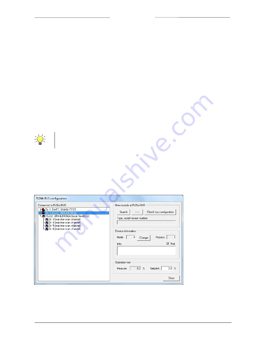
The


following


window


is


shown.


On


the


left


hand


side,


all


instruments


connected


to


the


FLOW

BUS


are


shown,


ordered


by


their


assigned


channel.


In


this


example,


two


digital


controllers


(channel


1


and


2)


and


one


RS232/FLOW

BUS


interface


with


4


real

time


channels


(channel


3


to


6)


are


connected.


On


the


right


hand


side,


the


top


frame


is


meant


to


add


legacy


modules


to


the


FLOW

BUS.


To


add


such


a


module,


connect


the


module


to


the


FLOW

BUS,


press


Search


and


follow


on

screen


instructions.


Communication


closes


automatically


when


FlowDDE


is


closed.


Содержание FlowDDE

Страница 1: ...ad this instruction manual carefully before installing and operating the instrument Not following the guidelines could result in personal injury and or damage to the equipment Head Office Nijverheidsstraat 1a NL 7261 AK Ruurlo The Netherlands Tel 31 573 458800 info bronkhorst com ...

Страница 2: ...cument is subject to change at any time without prior notification Bronkhorst reserves the right to modify or improve its products and modify the contents without being obliged to inform any particular persons or organizations The device specifications and the contents of the package may deviate from what is stated in this document Symbols Important information Discarding this information could ca...

Страница 3: ...RAMETER INFORMATION 8 4 OPERATION 10 4 1 BASIC COMMUNICATION TO INSTRUMENTS AND SERVING CLIENT APPLICATIONS 10 4 1 1 Communication settings 10 4 1 2 Open communication 11 4 1 3 Close communication 11 4 2 CONFIGURATION 11 4 3 SETTINGS 12 4 3 1 Poll time 12 4 3 2 System settings 12 4 3 3 Simulation mode 13 4 4 VIEW AND EDIT PARAMETERS 13 4 4 1 View parameters and values 13 4 4 2 Edit parameters 14 4...

Страница 4: ... 2 REFERENCES TO OTHER APPLICABLE DOCUMENTS Manuals and guides for digital instruments are modular General instructions give information about the functioning and installation of instruments Operational instructions explain the use of the digital instruments features and parameters Fieldbus specific information explains the installation and use of the fieldbus installed on the instrument 1 2 1 Man...

Страница 5: ...cause other problems as well See Microsoft s KB198098 To avoid communication errors it is advised to use a serial RS232 port with hardware buffer overrun detection Few USB RS232 converters have this feature but e g the Digitus part no DA 70156 has 1 5 INSTALLATION AND START UP Follow on screen instructions when installing FlowDDE FlowDDE will be installed in C Program Files Bronkhorst FlowDDE32 St...

Страница 6: ... a RS232 connector or as an integral 14TE module of your E 7000 or E 8000 readout and control system The converter offers communication with a baud rate up to 38400 baud Communication software support is available Communication settings are 38400 n 8 1 2 1 1 D connector for RS232 The female RS232 x sub miniature 9 pin D connector has the following pin configuration Pin number Description 1 2 3 4 5...

Страница 7: ...nt other instruments connected to the FLOW BUS can be communicated with as well RS232 communication is possible by 9 pin Sub D connector non IP65 instruments e g EL FLOW 8 pin DIN connector IP65 instruments e g CORI FLOW For the exact connections please advise your hook up diagram 2 2 1 Applications e g EL FLOW FLOW mass flow meter controller Power Supply Instrument supplied through the D sub DB 9...

Страница 8: ...a string with a length of X bytes 0 means no info required not a string type parameter Min Minimum value of parameter allowed when parameter is read written The value will be checked on this limit error when out of limit Max Maximum value of parameter allowed when parameter is read written The value will be checked on this limit error when out of limit Read Indication if parameter is allowed to be...

Страница 9: ...age will always be accepted regardless the true node address of the instrument on the bus The process can be found in the parameter table or has to be determined when nothing is filled in In that case the process number most often is 1 but on devices with e g multiple sensor channels the process will be 1 for the first channel 2 for the second and so on up to 32 On these modules also process 33 65...

Страница 10: ... 4 1 1 Communication settings Before communication to the instrument s can be made the communication settings have to be correctly configured Open the communication settings from the menu Communication Communication settings or by pressing F2 The window shown at the right hand side pops up At Interface the COM port and the baud rate can be selected For most interfaces the default baud rate is 3840...

Страница 11: ...d after each poll so clients don t need to actively refresh these before using From now on FlowDDE is ready for any client FlowDDE can be minimized and acts as silently as a server until the communication is closed 4 1 3 Close communication Communication to the instrument can be stopped by from the menu Communication Close communication or F4 Polling is stopped all DDE items are terminated and cli...

Страница 12: ...ged at Server Poll time The window at the right hand side pops up It contains three settings Poll time the time between two poll requests Batch of channels the number of channels that are polled at once The next poll time the next batch is polled This prevents high CPU loads due to many channels being polled but reduces the actual poll time per channel as the total number of channels is divided by...

Страница 13: ...writes all command to the instrument When the instrument returns an error that error is shown 4 3 3 Simulation mode In simulation mode only DDE communication with a virtual system stored in the database is possible This can be used when you don t have a FLOW BUS system available Parameter values can be read and write through DDE by your client Only controllers are simulated in this mode Sending a ...

Страница 14: ... the parameter number or close the window and answer the question by Yes Removing a parameter from DDE means that client applications cannot reach it and FlowDDE does not read the parameter value from the instrument To remove a parameter from DDE uncheck the Available at DDE checkbox By default all parameters are available checked Changing parameter information cannot be undone other than by reins...

Страница 15: ... well Copy a link from any application e g copy a cell from Excel In the test form press Paste Any change in the application s field result in the parameter value in FlowDDE to be updated Note that when the communication is closed all links will be terminated and will not be restored when the communication is opened again Disable standard polling temporarily stops FlowDDE from polling the selected...

Страница 16: ...of all parameters in group Y of channel X C 0 P 0 1 read values of all parameters of all channels Other special actions can be triggered by P 0 C 0 P 0 2 open a log file read all parameter values on all channels and close the file C 0 P 0 3 bring the main window to the front C 0 P 0 4 bring the FLOW BUS configuration window to the front C 0 P 0 6 bring the Poll time window to the front C 0 P 0 7 b...

Страница 17: ...DDE Server ComStatus Status of FlowDDE Idle Normal polling Simulation Scanning FLOW BUS Server OpenCom Communication status command 0 close 1 open Server MaxChan Maximum channel number in FLOW BUS configuration Server MaxNode Maximum node address in FLOW BUS system Server MaxPar Maximum parameter number in FlowDDE database Server SelChan Select channel for changing polling mode 0 all channels Serv...

Страница 18: ...2 dll to perform the low level communication to the FLOW BUS The Flowb32 dll has methods to easily send or request a parameter value to a certain node process and parameter and to get the answers From the calls to these methods it constructs the required FLOW BUS messages in the binary ProPar protocol sends these messages and receives and interprets the answers from the instruments Included in the...

Страница 19: ...sist you selecting the right product for your application Contact sales by e mail sales bronkhorst com For after sales questions our Customer Service Department is available with help and guidance To contact CSD by e mail support bronkhorst com No matter the time zone our experts within the Support Group are available to answer your request immediately or ensure appropriate further action Our expe...

Отзывы: