background image

MASS-STREAM

TM

 Manual Flow Switch D-6300/FS 

9.17.114A – edition: 2017-07 

Page 5 of 36 

Table of Contents 


1  SHORT FORM START-UP………………................................................................ 6 


2  FLOW SWITCH INSTRUMENTS D-6300/FS.......................................................... 7 
2.1  General……............................................................................................................. 7 
2.2  Installation............................................................................................................... 9 
2.3  Operation and Maintenance................................................................................. 10 
2.4  Output Variants of the Switch-Point……….…….………………………..……….. 11 
 

2.4.1  Variant 1  „OFF – ON – OFF“……..……………………………………….… 12  


2.4.2  Variant 2  „ON – OFF – ON“…..…..……………………………………….… 13  

2.5  Setting of the Switch-Point using the Multi-functional Display.…...……...….. 15 
 

2.5.1  Password Protection..………………………………………………………… 15 


2.5.2  Basis Settings in the 

ʹ

Alarm

ʹ

 Menu………………………………………… 17 


2.5.3  Example for Switch-Point settings „Minimum-Maximum-Alarm“..…… 18 


2.5.4  Adjustment of the Alarm-Reset Func

tion „automatic ↔ manual”…….

 22 

2.6  Specifications of MASS-STREAM

TM

 Flow Switch D-6300/FS………………….. 23 


2.6.1  Hook-up Diagram RS232 and Analog I/O, 8-pole round (male)..…….... 24 


2.6.2  8DIN Connector, 8-pole round (female)…............................................... 25 


3  MEASUREMENT PRINCIPLE AND CALIBRATION............................................. 26 
3.1  CTA Through-Flow Measurement....................................................................... 26 
3.2  Functional Block Diagram………........................................................................ 27


3.3  Calibration and Look-up Table............................................................................ 28 


4  OPERATION VIA RS232....................................................................................... 29 
4.1  Input Signal via FlowView.................................................................................... 31 


5  MANUAL INTERFACE: Micro Switches and LED’s……………………………… 34 


The dimensional drawings and hook-up diagrams of  the  MASS-STREAM

TM

  Digital 

Instruments  D-6300  are available for download on our website 
www.bronkhorst.com. 

Содержание D-6300/FS

Страница 1: ...low Switch Doc No 9 17 114A Date 27 07 2017 ATTENTION Before installing and operating the instrument it is strongly recommended that this instruction manual should be read carefully Not following the guidelines could result in personal injury and or damage to the equipment ...

Страница 2: ...StreamTM model series D 6300 The Bronkhorst manuals for multi bus instruments have a modular set up and include Mass StreamTM Instruction Manual D 6300 Digital Mass flow meters controllers document no 9 17 104 Mass StreamTM Instruction Manual D 6300 Multi functional Display document no 9 17 105 General instructions digital Mass Flow Pressure instruments laboratory style IN FLOW document no 9 17 02...

Страница 3: ...r example Any liability is explicitly excluded for any secondary damage caused by the instrument s failure or the malfunction of any component All wear parts like seals for example are also excluded from the warranty The products of M W Instruments GmbH are warranted against defects in material and workmanship for a period of three years from the date of shipment provided they are used in accordan...

Страница 4: ...shock etc Re conditioning of products primarily returned for warranty service that is partly or wholly judged non warranty may be charged for M W Instruments GmbH prepays outgoing freight charges when any party of the service is performed under warranty unless otherwise agreed upon beforehand However if the product has been returned collect to M W Instruments GmbH these costs are added to the repa...

Страница 5: ...r Switch Point settings Minimum Maximum Alarm 18 2 5 4 Adjustment of the Alarm Reset Function automatic manual 22 2 6 Specifications of MASS STREAMTM Flow Switch D 6300 FS 23 2 6 1 Hook up Diagram RS232 and Analog I O 8 pole round male 24 2 6 2 8DIN Connector 8 pole round female 25 3 MEASUREMENT PRINCIPLE AND CALIBRATION 26 3 1 CTA Through Flow Measurement 26 3 2 Functional Block Diagram 27 3 3 Ca...

Страница 6: ... by means of the correct cable The maximum cable length for communication via RS232 must not exceed 10 m Power Supply Make sure that the instrument or interface is connected to the power supply 15 Vdc up to 24 Vdc please check on instrument label COM Port Settings Use settings 38400 n 8 1 for your COM Port Baud rate 38400 Baud no parity 8 data bits 1 stop bit In case of any trouble during installa...

Страница 7: ...The Flow Switches are equipped with a digital electronic multi bus pc board and consist of a micro controller with peripheral circuitry for measuring and communication The flow signal is measured directly in the gas flow digitized and processed by means of the internal software firmware The measured and processed values can be output through the analog interface or through the digital RS232 commun...

Страница 8: ...ruments GmbH Dorfstrasse 1 D 85391 Leonhardsbuch Germany Tel 49 8166 9921 0 Fax 49 8166 9921 22 Email sales mw instruments com When the instrument needs to be returned please include a description of the damage in a closed envelope ATTENTION All instruments for return must have a fully filled in ʹDeclaration of Decontaminationʹ This declaration has to be attached to the shipping documents allowing...

Страница 9: ...front of the instrument Avoid piping with small diameter at high flow rates When possible no abrupt angles or other disturbances shall be mounted directly in front of the instrument All devices have Withworth pipe threads type RP according to ISO228 1 cylindrical G threads in inches according to BSPP The mounting of NPT fittings will destroy the inlet threads in the instrument s body Using an inle...

Страница 10: ...nds using standard cables following the CE requirements and could supply them when needed 2 3 Operation and Maintenance When the power is switched on a warm up period of at least 30 sec is required allowing the instrument s thermal stabilisation Afterwards the instrument will work with an accuracy of approximately 4 FS It takes around 30 minutes until the optimal stability is reached and the instr...

Страница 11: ...ntical to the supply voltage 15 24 Vdc for the operation of the Flow Switch Applying variant 1 OFF ON OFF and according to one of the 3 selectable switching variants see 2 4 1 a 2 4 1 c the Flow Switch forwards a voltage to Pin 5 of the 8 pole instrument connector when the switch point for example minimum alarm has been activated Applying variant 2 ON OFF ON and according to one of the 3 selectabl...

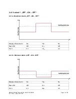
Страница 12: ...edition 2017 07 Page 12 of 36 2 4 1 Variant 1 OFF ON OFF 2 4 1 a Maximum Alarm OFF ON OFF Display shows Alarm No Yes No Red LED Off On Off Pin 5 0 V Us 0 V 2 4 1 b Minimum Alarm OFF ON OFF Display shows Alarm No Yes No Red LED Off On Off Pin 5 0 V Us 0 V ...

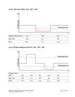
Страница 13: ... 07 Page 13 of 36 2 4 1 c Minimum Maximum Alarm OFF ON OFF Display shows Alarm No Yes No Yes No Red LED On Off On Off On Pin 5 0 V Us 0 V Us 0 V 2 4 2 Variant 2 ON OFF ON 2 4 2 a Maximum Alarm ON OFF ON Display shows Alarm No Yes No Red LED Off On Off Pin 5 Us 0 V Us ...

Страница 14: ... edition 2017 07 Page 14 of 36 2 4 2 b Minimum Alarm ON OFF ON Display shows Alarm No Yes No Red LED Off On Off Pin 5 Us 0 V Us 2 4 2 c Minimum Maximum Alarm ON OFF ON Display shows Alarm No Yes No Yes No Red LED Off On Off On Off Pin 5 Us 0 V Us 0 V Us ...

Страница 15: ...d or numbers are selected and set with Enter Pressing Up will show letters in alphabetical order first small letters then capitals and the numbers 0 9 come last Pressing Down will show the numbers first being then followed by capitals and small letters in reversed order Blanks are generated with Enter The device has an adjustable screen saver which will be de activated by pressing Enter once 2 5 1...

Страница 16: ... 6300 FS 9 17 114A edition 2017 07 Page 16 of 36 Enter activates the data field for the password Select required letters or figures with Up and Down and confirm each selection with Enter Enter 1 x Up Enter 2 x Up 3 x Up Enter 5 x Enter ...

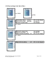
Страница 17: ...nter ʹModeʹ factory setting min max FIX do not change ʹResetʹ factory setting automatic see page 18 5 x Down ʹSetpoint stepʹ factory setting no FIX do not change 1 x Down ʹMin alarmʹ operator input see example ʹMax alarmʹ operator input see example ʹDelayʹ factory setting 0 see page 18 ʹSetpointʹ factory setting 0 0 FIX do not change ...

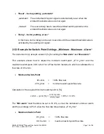
Страница 18: ...Minimum Maximum Alarm The instrument only accepts values in for setting the Min alarm and Max alarm This example shows how to adjust the minimum switch point 27 8 ln min and the maximum switch point 38 5 ln min for a Flow Switch instrument which is calibrated for a flow rate of 45 ln min Minimum Switch Point 45 ln min 100 flow rate 27 8 ln min minimum switch point flow rate Calculation of the requ...

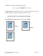
Страница 19: ...in Switch point 38 5 ln min 45 ln min 100 85 6 The ʹMax alarmʹ must therefore be set to 85 6 so that the instrument emits an alarm and thus a voltage to Pin 5 when the flow rate exceeds 38 5 ln min Input of the Switch Points via the Multi functional display Select Min alarm with Down and activate this menu item with Enter Down Enter ...

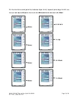
Страница 20: ...edition 2017 07 Page 20 of 36 For the minimum switch point the individual digits of the required percentage ʹ61 8 ʹ are now set with Up and Down in the menu item Min alarm and activated with Enter Enter 4 x Down Enter 1 x Up Enter 2 x Down Enter 1 x Down ...

Страница 21: ... 2017 07 Page 21 of 36 In the next step the individual digits for the maximum switch point of the required percentage ʹ85 6 ʹ are now set with Up and Down in the menu item Max alarm and activated with Enter Enter Enter 2 x Down 5 x Up Enter Enter 4 x Down Enter ...

Страница 22: ...d to be repeated accordingly If only the minimum switch point is required the corresponding data input has to be entered in the menu item Min alarm and the data in Max alarm remains ʹ0 0 ʹ If only the maximum switch point is required the corresponding data input has to be entered in the menu item Max alarm and the data in Min alarm remains ʹ0 0 ʹ 2 5 4 Adjustment of the Alarm Reset Function automa...

Страница 23: ... Parts Sensor Stainless steel SS316 AISI 316L Instrument body Aluminium AL 50ST 51ST anodised or Stainless steel SS316 AISI 316L Sieves Stainless steel SS316 AISI 316L Distance parts Teflon or Stainless steel Protection IP65 Operating Limits Measuring range up to 1 100 1 100 Temperature 0 50 C Pressure 0 10 bar g for aluminium body 0 20 bar g for stainless steel body Warm up time 30 min for optimu...

Страница 24: ...MASS STREAMTM Manual Flow Switch D 6300 FS 9 17 114A edition 2017 07 Page 24 of 36 2 6 1 Hook up diagram RS232 and Analog I O 8 pole round male ...

Страница 25: ... to PLC Only shielded wire terminals can be used SERIE 423 99 5672 19 08 8 DIN CONNECTOR BINDER O RING DETAIL THE CABLE THE SHIELD MUST BE AROUND FOLD THE SHIELD OF THE CABLE BACK OVER DETAIL CONNECTED TO THE CONNECTORHOUSING SHIELD OF THE CABLE SHOULD BE BLACK TUBING THE CABLE CABLE LIYCY 8x0 25mm 4 0 20 mm 2 SHRINK SOLDERCONTACTS WITH SHRINKTUBING BRE 160 BLACK OR EQ 7 3 8 5 2 6 1 4 solder side ...

Страница 26: ...of gas flow or liquid flows published in 1914 Two elements a heater and a temperature probe are positioned in the gas flow CTA is aiming to keep the difference in temperature T between both sensor pins at a constant level The flow rate and the heater energy required to maintain this constant T are proportional and thus indicate the mass flow of the gas The relation between the heater energy and th...

Страница 27: ...am Mass flow meter DMFM The sensor signal is digitised via ADC and processed internally Being reconverted from digital to analogue the signal is forwarded as reading on the analogue output by means of current or voltage The reading is also available as 2 byte integer at parameter 8 and can be readout via RS232 ...

Страница 28: ...d to each specific mass flow To generate and store the look up table in the instrument up to 21 measurement points are recorded and equally arranged over the total measurement range Using the look up table the instrument s firmware relates the correct gas flow to each raw signal via interpolation This method allows processing almost any sensor raw signal given that the signal is monotonically incr...

Страница 29: ...er software it can be found on the CD which is accompanying the despatched goods FlowDDE is required for the following software operations Set up communication between device and computer Hook up of the instrument following the schematic description in chapter 2 5 Start of FlowDDE and select the COM Port connected to the instrument Set the Arbitration to Autobusmaster optimize then select Paramete...

Страница 30: ...ing selected the COM Port and Baud Rate you need to start the communication between a personal computer and the instrument via F3 or by clicking on the menu ʹCommunicationʹ being followed by a second click on ʹOpen communicationʹ FlowDDE on your monitor should show the following picture ...

Страница 31: ...standard operations FlowView can be found on the CD which is accompanying the despatched goods and can be down loaded from http downloads bronkhorst com Covered functions Actual reading Alarm functions configurable Counter functions configurable Operations procedure Start FlowDDE and open the communication Start FlowView The following pictures should be displayed example ...

Страница 32: ...tch D 6300 FS 9 17 114A edition 2017 07 Page 32 of 36 Alarm function adjustments The adjustment of alarm functions is well supported by FlowView Click on the button ʹAlarm Counterʹ to open a frame for the adjustment of all settings ...

Страница 33: ...MASS STREAMTM Manual Flow Switch D 6300 FS 9 17 114A edition 2017 07 Page 33 of 36 ...

Страница 34: ...itch is not pressed the green and red LED are used for the mode indication see table 1 and 2 When the switch is pressed down both LED s will be switched off for function selection As long as the switch will be pressed down there will be a change in indication by both LED s after each 4 seconds The moment the indication LED pattern for the wanted function is recognised the switch must be released t...

Страница 35: ...wView the instrument can wink with LED s to indicate its position in a large system normal wink 1 sec on 1 sec off Alarm indication Minimum alarm limit maximum alarm Power up alarm or limit exceeded or batch reached fast wink 0 1 sec on 0 1 sec off Switch released selected action started Please note wink green red green red in steady turn by turn Table 2 Red LED indications on digital instruments ...

Страница 36: ... NOTE First ensure there is no flow and instrument is connected to power for at least 30 minutes on on 12 16 sec Prepare instrument for FLASH mode At next power up FLASH mode will be active This mode will be indicated by both LED s off when instrument is normally powered Please note on short flash 0 1 sec on 2 sec off Table 4 LED indications using micro switch at power up situation of an instrumen...

Отзывы: