7
7. INSTALLATION IN LIGHTWEIGHT WALLS
1 Before commencing installation, check the condition of the damper, the correct position of the shutter, in a closed
position, and that the command works properly. The plasterboard panels to be used are of type F according to EN
520 and DIN 18180 and have unit thickness of 12,5 mm.
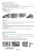
2 Make a hole in the metal structure wall which is 140 mm large in H and L than the nominal damper measurements.
The metal structure must comply with the measurements indicated in the diagram. Fill in the spaces inside the
metal structure using mineral wool which 60 mm thick and has a minimum density of 100 kg/m³ (fig.1).
3 Cover both sides of the metal structure with two layers of plasterboard, each 12.55 mm thick, leaving enough space
to install the fire damper unit. The wall will hence have a total thickness of 125 mm. Cover the perimeter of the
damper housing seat with a double layer of plasterboard laths, 125 mm long and 12.5 mm thick. The measurements
of the empty hole will now be 90 mm larger than the nominal damper measurements (fig.2).
4 Fasten the 4 accessory metal brackets to the screws protruding from the corner of the damper thermal cut, making
sure that the side of the bracket supporting the damper does not protrude over the outer edge of the flange. Use the
threaded bolts supplied with the brackets to fix them in place (fig.3).
5 Position the damper inside the hole centring it horizontally, making sure the shutter axis corresponds to the wall
axis. Maintain the axis of rotation of the blade horizontal as from tests carried out (is not allowed to be installed with
vertical axis). Check that the damper protrudes from the wall by the correct measurement, bringing the previously
installed metal brackets up against the wall (fig.4).
6 Fill in the space between the wall and the damper using specifically sized plasterboard laths, using gypsum based
adhesive to fill in any remaining holes (fig.5).
7 Reinforce the walls with a double layer of plasterboard panels (length = 150 mm + nominal damper size / width =
150 mm / thickness = 12.5 mm) on both sides of the damper, making sure to create a suitably sized compartment
in the external panel to house the control unit. (fig.6).
On completing installation, it is recommended to run a test to check the blade rotates correctly and the commands
work properly (in both manual and motorised mode). It can be conducted in manual mode by using the lever to reset
the damper and pressing the test button to simulate operating functions. In motorised mode, use the thermoelectric
fuse lever.
fig. 4
fig. 1
fig. 5
fig. 2
fig. 6
fig. 3


