Brofer MDF30EURO Скачать руководство пользователя страница 4

4

3. HANDLING AND INSTALLATION WARNINGS

WARNING!

• All handling and installation operations must be conducted with the fire damper shutter in a closed position (as per 

our standard supply).

• All connections to the mains must be done by professionally qualified personnel.

• Clean and remove all cement residues from the connection flanges to ensure secure connections to the rest of the 

duct.

• Avoid all deformation of the duct and/or obstacles inside the duct that could prevent correct rotation of the shutter

• Check there are no external objects (cables, pipes, etc.) which could prevent the correct operations of the commands 

outside the duct itself

• Keep as much access clearance as possible on the control unit side so as to ensure the user and maintenance 

operators have sufficient space to work on the damper.

4. MAINTENANCE

No special maintenance is required. It is however recommended to check that all shutter operating and warning devic-

es are working properly on a regular basis. More specifically, check for complete and correct opening and closing of the 

shutter blade: for information on how to enable the commands, please refer to the “COMMAND FUNCTION” paragraph 

on page 6 of this manual. Also check that the limit switch warning devices for start and end strokes (where applicable) 

are in good working condition.
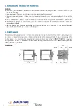
DIMENSIONAL

Содержание MDF30EURO

Страница 1: ...making air better MDF30EURO INSTALLATION AND OPERATION MANUAL FIRE PROTECTION EN...

Страница 2: ...RK 3 3 HANDLING AND INSTALLATION WARNINGS 4 4 MAINTENANCE 4 5 INSTALLATION IN BRICK WALLS 5 6 INSTALLATION IN CONCRETE FLOORS 6 7 INSTALLATION IN LIGHTWEIGHT WALLS 7 8 CONTROL FUNCTIONS 8 9 REPLACING...

Страница 3: ...has been installed the control unit will remain outside the masonry to make post installation interventions easier When installed following the instructions provided in this manual it can be used in H...

Страница 4: ...ch could prevent the correct operations of the commands outside the duct itself Keep as much access clearance as possible on the control unit side so as to ensure the user and maintenance operators ha...

Страница 5: ...d to be installed with vertical axis Respect the dimensions shown fig 2 table 1 4 Fill in the space between the wall and the damper using fireproof cement material M10 cat or higher to reinstate resis...

Страница 6: ...inst the damper casing so that it is blocked in the correct position fig 2 5 The metal brackets are designed to be fastened to the floor fig 3 6 Fill in the space between the floor and the damper usin...

Страница 7: ...he side of the bracket supporting the damper does not protrude over the outer edge of the flange Use the threaded bolts supplied with the brackets to fix them in place fig 3 5 Position the damper insi...

Страница 8: ...lectromagnetic circuit breaker Reset Power up the electromagnet electrical wiring diagram on page 8 Raise the metal lever on the control unit casing fig 1 Remove the reset lever from the housing compa...

Страница 9: ...he key supplied with the delivery into the housing on the servomotor and turn it counter clockwise by half a turn to enable the spring return that will automatically move the servomotor into the close...

Страница 10: ...Switch technical data Casing Fibre glass reinforced thermoplastic Protection rating EN 60526 Standard IP65 Cable cross section diameter rigid 2 5mm flexible with ferrule 1 5 mm Operating temperature...

Страница 11: ...device consists of three fuses these make the fire damper shutters sensitive to the temperature inside the duct with Tf 2 and Tf 3 fuses which can be replaced and to ambi ent temperatures using the Tf...

Страница 12: ...rofer it INSTALLER 19 143 43 211 70 55 500 210 21 30 051 Fax 210 22 23 283 BROFER SRL Via Roma 66 31023 Resana TV Italy Tel 39 0423 716611 Fax 39 0423 716612 info brofer it www brofer it making air be...

Отзывы: