background image

3

2

1

1 = RED

2 = YELLOW

N = BLACK 

1

4

2

4

1 = RED

4 = YELLOW

5

6

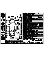
Electrical Box Assembly

7

ITEM NO.

PART NUMBER

DESCRIPTION

QTY.

1

-

Nut M16

1

2

9104010

Swing Handle

1

3

9105040

Deadman Trigger

1

4

MS

Micro Switch

1

5

Cable

Cable White

1

ITEM NO. PART NUMBER

DESCRIPTION

QTY.

6

9615500

XLR Line Plugs 

AC3MM PD5302

1

ITEM NO. PART NUMBER

DESCRIPTION

QTY.

7

9615490

XLR Socket PD5367

1

ISSUED DATE 25.07.2017

DRAWN BY ANH

PART NO.

SCALE:NTS

SHEET 1 OF 1

A4

9301040

TITLE:

DEADMAN TRIGGER 

ASSEMBLY

BROBO GROUP

Содержание S315D, S350D, S400B

Страница 1: ...ANCE MANUAL OHS SERIES METAL SAWS MODEL No S315D S350D S400B Serial No s C 29680 BROBO GROUP AUST PTY LTD A C N 098 264 316 A B N 42 098 264 316 8 Fowler Rd Dandenong 3175 PO BOX 4274 Dandenong Sth 3164 Victoria AUSTRALIA Tel 61 3 9794 8751 Email info brobo com au Fax 61 3 9794 8792 Website www brobo com au Quality Endorsed Company ISO 9001 Lic 10292 SAI GLOBAL Quality System YOUR BROBO DISTRIBUTO...

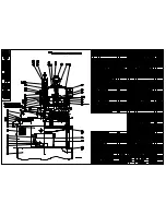
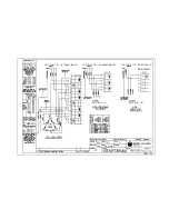
Страница 2: ... Assembly Drawing 2 of 3 4 1 3 Assembly Drawing 3 of 3 4 2 1 Electrical Circuit 1PH 3PH 3PH Dual Speed Circuit Diagram 4 2 2 Electrical Circuit 3PH with Dead Man Trigger DMT 4 2 3 Diagram For Connection 1PH 3PH Circuit 4 2 4 Component Layout Electrical Schematic Drawings 3PH 4 3 1 Cold Saw Main Dimensions 4 3 2 Cold Saw Assembly 4 3 3 Standard Gearbox Assembly 4 3 4 Deadman Trigger Assembly 4 3 5 ...

Страница 3: ...180 80 1 300 320 360 2 200 220 240 3 200 200 220 4 160 180 180 5 140 160 180 100 1 300 300 340 2 220 200 220 3 200 180 180 4 160 140 160 5 140 120 140 120 1 300 340 2 200 220 3 180 180 4 160 160 5 120 140 SOLID SECTIONS 10 280 280 300 20 160 200 240 30 140 160 200 40 120 140 140 50 80 100 120 60 80 100 TABLE 2 Blade Selection Chart NOTE CHART GUIDE ONLY This chart is issued as a guide only Many ot...

Страница 4: ... 50Hz Power Supply 3 415 1420 2680 1 5 2 2 50Hz Power Supply 3 415 650 1350 1 1 1 5 60Hz Power Supply 1 230 1700 1 7 60Hz Power Supply 3 220 850 1700 1 1 1 5 60Hz Power Supply 3 440 850 1700 1 5 2 2 60Hz Power Supply 3 220 1700 3400 1 1 1 5 TABLE 3 Motor Specifications BLADE SPINDLE RPM Motor Type BLADE SPEEDS S315 S350 S400 Frequency Hz Phase RPM RPM m min RPM m min RPM m min 50 3 650 21 20 21 23...

Страница 5: ...3 6 8 90 50 STD 2 AUTO 3 60 STD 2 3 4 AUTO 3 1 2 60 STD 2 3 4 AUTO 3 1 2 Note The above values are based on a full size blade The capacities will reduce accordingly when a worn blade is resharpened DIMENSIONAL SPECIFICATIONS Base Dimensions L W 550mm 660mm Table Working Height 968 mm Saw Height 1917 mm SAW WEIGHT Un Packed Weight kg Packed Weight kg S315 S350 S400 Saw Unit 136kg 300lb 150kg 330lb ...

Страница 6: ... area as close as possible to the final location Carefully remove the wooden frame surrounding the saw unit Figure 1 Once completed proceed by elevating the machine away from the pallet base using a sling harness wrapped around the cutting head of the saw Ensure that the floor is as level as possible before finally positioning the machine to the desired location FIGURE 1 Handling of Metal Cutting ...

Страница 7: ...al Mechanical Vice Clamp Manual Mechanical Dual Arm Vice Clamp 9501740 Fabricated Sheet Metal Stand 9301450 Floor Stand Angle Iron 9301400 Trigger Deadman Switch 9501640 S350D S400B Brobolube Additional Blade s Custom to Client Requirements 1 3 Minimum Requirements For the machine to function correctly the room in which the saw unit is to be installed must be in the vicinity of and satisfy the fol...

Страница 8: ...applicable in which the saw head rests on is anchored to the floor by 4 M12 bolts provided For added stability it is strongly recommended that the machine stand be fastened to the floor by using loxins not provided When positioning and fastening the unit please refer to the hole locations shown in Figure 2 Figure 2 Anchoring Hole Locations FRONT OF MACHINE FRONT OF MACHINE FRONT OF MACHINE FRONT O...

Страница 9: ...d with a suitable approved four pin plugs i e three phase and earthing not provided Figure 3 2 Connection for 4 CORE Wire System with Neutral 3 Phase c Check the power supplied and motor specifications before plugging in the machine Check terminal connection on dual voltage motor terminal box and connect it accordingly to the corresponding voltage supply d If dual motor is requested the motor is a...

Страница 10: ... Control Switch 3 Check that the motor is operating in the correct direction that is the blade is rotating downwards and into the direction of the vice clamps 4 Ensure that all electrical leads and cables including supply leads are maintained in a good condition and away from sharp objects All leads should be replaced if cut sliced or damaged in any way Brobo Group S315 S350 S400 Series Metal Cutt...

Страница 11: ...CTIVE ON MACHINERY No 98 37 CE Danger Zone any zone in and or around a machine in which the presence of a person constitutes a risk for the safety and health of that person Person Exposed any person finding him or herself either completely or partly in a danger zone Operator the person or persons given the responsibility of installing operating adjusting maintaining cleaning repairing and transpor...

Страница 12: ...uirements Lighting Insufficient lighting during the operation of the saw unit would constitute a safety hazard for the people concerned For this reason the user of the machine must provide adequate lighting in the working area to eliminate areas in shadow whilst also preventing dazzling illumination sources Reference standard ISO 8995 2002 Lighting of Indoor Workplaces Connection Check that the po...

Страница 13: ...e tied back or placed in a hair net Always disconnect the power supply to the machine before carrying out any maintenance work or adjustments This includes cases of abnormal operations of the machine Any maintenance work performed on the hydraulic pneumatic or coolant systems must be carried out only after the pressure in the system has been released The operator MUST NOT conduct any risky operati...

Страница 14: ...ays follow safe practices and inspection procedures when installing blades Please refer to section 5 1 Changing the Blade When cutting very small specimens ensure that the workpiece is not dragged behind the back fence support where it could get lodged behind the blade If the blade jams during a cut activate the emergency stop function immediately Do not continue forcing the blade through This cou...

Страница 15: ...he saw also complies with the Australian Standards regarding the safeguarding and general requirements for electrical equipment 2 4 1 Reference Standards MACHINE SAFETY EEC Directive No 98 37 CE Machines Directive EEC Directive No 91 368 94 68 Amends sections of EEC Directive No 98 37 CE relating to machine safety EEC Directive No 73 23 Low Voltage Directive AS4024 1 1996 Safeguarding of Machinery...

Страница 16: ...rrect saw blade provides minimum burr to the work piece while maximising the safety to the operator during each cutting procedure 3 1 2 Saw Safety Guard The primary purpose of the saw safety guard is to protect the user from the spinning blade It also functions as a safety device to protect the operator from any broken tooth swarf or high velocity particles that might be dislodged by the cutting p...

Страница 17: ...ector Switch The rotary Main power switch also serves as the speed selector switch When the speed is selected the saw is set to STANDBY mode The STANDBY lamp illuminates to provide a warning to personnel the saw is at the ready AT any time the Dead Man trigger is activated the saw will run 3 1 5 Manual Vice Clamp The manual vice clamp lever allows speedy clamping of material with ergonomically des...

Страница 18: ...equired whenever the head angle is altered 5 For pneumatic vices set the vice clamping pressure from the pressure regulators located on the main control unit door If for any reason this pressure is not available on a continuous basis the regulator on the air service unit must be set slightly below the available line pressure and the safety low pressure indicator valve needs to be reset to correspo...

Страница 19: ...e material and cross sectional dimensions When cutting stainless steel or high carbon steel Brinell hardness above 200 the slowest speed machine should be used together with a cobalt type high speed steel blade When manually feeding the saw head keep in mind to maintain a steady continuous pressure thus avoiding work hardening on the cutting piece Avoid forcing the blade through the material as th...

Страница 20: ......

Страница 21: ......

Страница 22: ......

Страница 23: ......

Страница 24: ......

Страница 25: ...THREE PHASE ONE PHASE COMPONENT SCHEMATIC WIRING DIAGRAMS FOR CONNECTION FOR 1 PHASE OR 3 PHASE CIRCUIT ...

Страница 26: ......

Страница 27: ...ELECTRICAL DIAGRAM 2 Speed Switch 1 0 2 ...

Страница 28: ...0 844 1917 1480 890 968 TOP VIEW SIDE VIEW NOTE MINIMUM 600MM ALL AROUND SAFE SPACE FOR OPERATING ZONE BROBO GROUP COLD SAW MAIN DIMENSIONS TITLE A4 SHEET 1 OF 1 SCALE NTS ISSUED DATE 25 08 2017 DRAWN BY ANH ...

Страница 29: ...5 3 17 8705130 Screw M8x25 1 16 8705340 Hex HD Cap M6x16 2 15 9324270 Spring Bracket Lower 1 14 9512030 Pivot Block 1 13 8705440 SH Shoulder M10 1 12 9542050 Outer Guard 1 11 9312020 Rotary Table 1 10 9332060 Back Fence Assembly 2 9 9305110 Grease Nipple M8 1 8 8705270 Soc HD Cap M12x60 2 7 8705300 Soc HD Cap M12x100 2 6 9312000 Clamping Table 1 5 9540000 Electrical Box Assembly 1 4 9301040 Deadma...

Страница 30: ...ing ML100 24mm 1 15 8725770 Screw Soc HD Cap M8x30 4 16 9504120 Spacer 39x24x14 1 17 Motor 1 18 8705090 Screw Soc Hex HD Cap M6x35 3 19 9302110 Side Cover Plate 1 20 8705420 Screw Flat Head M10x25 1 21 9304130 Retainer Washer 55x10 1 22 9314420 Key Main Spinder 1 23 9305010 Seal 1 24 9314050 WormWheel 1 25 9504080 Main Spindle S315 S350 1 26 9502040 Inner Guard 1 27 9105050 Coolant Tap 1 28 870505...

Страница 31: ...ng Handle 1 3 9105040 Deadman Trigger 1 4 MS Micro Switch 1 5 Cable Cable White 1 ITEM NO PART NUMBER DESCRIPTION QTY 6 9615500 XLR Line Plugs AC3MM PD5302 1 ITEM NO PART NUMBER DESCRIPTION QTY 7 9615490 XLR Socket PD5367 1 ISSUED DATE 25 07 2017 DRAWN BY ANH PART NO SCALE NTS SHEET 1 OF 1 A4 9301040 TITLE DEADMAN TRIGGER ASSEMBLY BROBO GROUP ...

Страница 32: ...D Capscrew M12x60 LG 2 10 9312050 Vice Block 1 11 9304170 Quick Action Nut 1 12 9314020 Vice Screw 1 13 9301440 Handle Crank 1 14 8705940 Rollpin 4x24 LG 1 15 1045020 Knob 38x M12 1 16 9314090 Quick Action Handle 1 17 8735380 Rollpin 8x40 LG 1 18 9314280 Vice Block Clamp 2 19 8705980 Rollpin 6x16 LG 1 20 9405090 Compression Spring 2 21 8705460 Screw Flat HD M5x8 LG 2 22 8726100 Socket Button Head ...

Страница 33: ...Nut 1 12 9314020 Vice Screw 1 13 9301440 Handle Crank 1 14 8705940 Rollpin 4x24 LG 1 15 1045020 Knob 38x M12 1 16 9314090 Quick Action Handle 1 17 8735380 Rollpin 8x40 LG 1 18 9314280 Vice Block Clamp 2 19 8705980 Rollpin 6x16 LG 1 20 9405090 Compression Spring 2 21 8705460 Screw Flat HD M5x8 LG 2 22 8726100 Socket Button Head Cap Screw M6x16 4 23 9302260 Extension Arm Block 1 24 9302250 Side Exte...

Страница 34: ...of any dirt or swarf that was trapped by the previous cutting cycles 5 Place the old saw blade into the new blade packaging and disposed of it safely Carefully mount the new blade onto the spindle hub ensuring that the blade is rotating into and towards the back fence and replace the counter plate utilising the drive pins as guides as it passes through the pinholes on the blade 6 Rotate blade back...

Страница 35: ...o extend the life of the blade maintain a firm and steady pressure whilst allowing the blade teeth to cut at an optimum rate Do not force the blade through the material This could cause numerous problems including breaking the blade teeth jamming the blade with the cutting part or fracturing the blade spindle The cutting action also generates a large amount of heat within the cutting sample due to...

Страница 36: ...increase the flow rate excessively because No significant increase in blade life or lubricating efficiency will be achieved confirmed by test results Excessive application of Brobolube will only result in a waste of fluid Excessive application will produce swarf that will be wet oily and harder to clean up than dry swarf produced from the correct supply of Brobolube ii The amount of Lubricant when...

Страница 37: ...l should be transferred into non porous containers of suitable strength Any remaining oil should be cleaned up with sand or other non combustible absorbent material Place the sand and oil mixture into containers and disposed of by an EPA approved landfill or alternatively by a suitable non polluting method In addition rags soaked in oil should not be burned Do not pour oil down the drain which wou...

Страница 38: ...ower switched off and the machine in emergency stop condition To guarantee for optimum operation all spare parts must be Brobo Group originals On completion of maintenance works ensure that the replaced parts or any tools used have been removed from the machines before starting it up Any behaviour not in accordance with the instructions for using the machine specified in this manual may create haz...

Страница 39: ...p any unpainted surfaces lightly oiled to protect from rust and corrosion 7 The air supply for the pneumatic air vices should be checked regularly such that it is free of any condensed water molecules and the filter should be drained frequently 8 Ensure that the machine performs cuts perpendicular to the work surface If not contact Brobo Group engineering department 9 Test that the blade is at rig...

Страница 40: ...h as reference set the stops at 45 left and right using the method described in Section 5 2 Adjusting the Cutting Angle Adjust the blade using the appropriate screws such that it is perpendicular to the work surface Check the hardness of the material being cut corresponds within the capabilities of the blade Check the water and oil mixture check that the holes and or hose are not blocked direct th...

Страница 41: ...tory Specimen vibrates in the vice check that the vice clamps are position correctly and the clamping pressure are adequate The blade slide runs over the material without cutting it increase or decrease head speed respectively Reduce cutting pressure Check the coolant level and clean piping and nozzles The material present may not be homogenous either on the surface such as oxides or sand present ...

Страница 42: ...ulic oil level and pressure system Blocked coolant tubing Ensure that the main power cable is plugged in and switched on Check the phases cables plugs and sockets for loose connection Also check that the motor connections are in place Verify that the contactors are not loose If contacts are short circuited contact Brobo Group engineering department immediately Check that it has not burnt out that ...

Страница 43: ...s below 85 dB A If the noise level becomes too high during a cutting cycle stop the process and inspect for problem if any are present Substance Low Care must be taken as some coolants may be harmful or cause allergic reactions Please read the labels carefully Keep the work area clean and regularly remove excess coolant oils and other impurities Hazardous Events Unexpected Start Up Low During a po...

Страница 44: ...WRITING HOWEVER JTA DO NOT WARRANT THEIR ACCURACY AND DISCLAIM ALL RESPONSIBILITY FOR ANY LOSS OR DAMAGE WHICH MAY BE SUFFERED BY ANY PERSON DIRECTLY OR INDIRECTLY FROM THE USE OF THIS REPORT Jeremy Trotman Assoc P L Procedures Development Noise On site Audiometric PO Box 246 Brighton Victoria 3186 Policy Manuals Confined Spaces Testing Telephone 03 9591 0733 Fax 03 9591 0776 Legal Compliance Audi...

Страница 45: ...ponents or other items together with the likely use materials used as part of the process cleaning procedures and maintenance procedures are some of the items given due consideration as to the likelihood of presenting Health and Safety risks to personnel These items identified as hazards are described under the heading of Hazard The Hazard listed in column 1 of the Risk Assessment RISK The level o...

Страница 46: ...sible L L L L M S Consequence Disaster 5 Exposure 1 Very Rare 2 Rare 3 Infrequent 4 Occasional 5 Frequent 6 Continuous Probability 6 Almost Certain H V V V V V 5 Quite possible S H V V V V 4 Unusual but possible M S H V V V 3 Remotely Possible L M S S H V 2 Conceivable L L M M S H 1 Practically Impossible L L L L L M Consequence Very Serious 4 Exposure 1 Very Rare 2 Rare 3 Infrequent 4 Occasional ...

Страница 47: ...Impossible L L L L L L Consequence Substantial 2 Exposure 1 Very Rare 2 Rare 3 Infrequent 4 Occasional 5 Frequent 6 Continuous Probability 6 Almost Certain L M S H V V 5 Quite possible L L M S H H 4 Unusual but possible L L L M M S 3 Remotely Possible L L L L L M 2 Conceivable L L L L L L 1 Practically Impossible L L L L L L Consequence Minor 1 Exposure 1 Very Rare 2 Rare 3 Infrequent 4 Occasional...

Страница 48: ...e of the method used to calculate the risk scores with the aid of the Matrices Sample Risk Assessment table excerpt Hazard Risk Score Control Recommendation Action Taken Yes No Re Score Rotating blade in reach of operator at normal work station of shift Severing injury risks RISK SCORE 6 5 4 V Consequence Very Serious 4 Permanent disability loss to 1 000 000 Probability Quite Possible 5 Quite poss...

Страница 49: ...ssessment TERMS OF REFERENCE The Risk Assessment shall be conducted by a competent assessor the assessor shall take into account The actual use of the plant Constructive comments and input from operators Appointed employee OHS representative group State of Knowledge of the type of Plant Applicable Australian Standards FOLLOW UP This report has been prepared in an easy to use format The Action Take...

Страница 50: ...arry out insulation leakage tests to all hazardous voltage mains power electric components and associated metal work Check earth continuity resistance to all metal frames and attachments Provide or repair earth points as necessary in accordance with AS 3000 AS NZ 3760 5 2 3 M 415 240 volt power supply Electric shocks burns electrocution risks RISK SCORE 6 5 4 V Fit DANGEROUS VOLTAGE and or ISO int...

Страница 51: ...lant regulations and Australian Standards RISK SCORE 4 5 5 V Fit identification function operating and direction signs to all controls including function and direction indication ie ON OFF SLOW FAST in accordance with R 306 1 of the Plant regulations Signs must be permanent and indelible in accordance with AS 1319 4 1 2 L Unauthorised use of plant Cutting injuries eye injuries severing risks RISK ...

Страница 52: ...pment Opening of incorrect circuits during maintenance incorrect maintenance non compliance with industry standards And building code Maintenance personnel operator injury risks Striking injuries eye injuries burns injuries electric shock injuries electrocution injuries RISK SCORE 5 5 3 V Fit identification signs to all hazardous voltage circuits Fit ISO type colour coded identification and flow d...

Страница 53: ... back injury risks crushing injury risks RISK SCORE 3 4 5 H Carry out Job Safety Audit on procedure to suit handling of materials onto machine write Safe Work Procedure accordingly display S W P in proximity to machine Introduce no lift policy to safety induction training 3 4 5 M Cutting coolant Poisoning injury risk RISK SCORE 3 2 4 L Fit safety instruction signs in accordance with cutting lubric...

Страница 54: ...ments of the Occupational Health and Safety Act 2004 Signed Dated 01 May 2009 Theo Avgoulis Plant Inspector ASIA Certification is applicable only to current product specifications Certificate of AS 4024 AS 3000 compliance fax 07 31124182 email info avgoservices com web www avgoservices com P O Box 5089 Garden City 3207 Victoria 3207 avgoservices Brobo S315 A D S SCV 350 D S SCV 400 B OHS Series Me...

Страница 55: ......

Отзывы: