page 4
TOOL LISTING
Depending on the installation, the use of the following tools
may be required. The power tools are recommended to make
the installation proceed quickly. A mask should be worn when
cutting ducting and gloves when using glue.
Wire strippers, 1/4’’ and 1/2” drill bits, utility knife, putty knife,
2½’’ hole saw, keyhole saw, hammer, cold chisel, level,
flashlight, drill, electrical tape, screwdriver, wrench, hacksaw,
tape measure, safety glasses.
WORKING WITH PLASTIC TUBING
CUTTING TUBING
Measure the length of tube needed. Allow 5/8” of tubing for
inserting into fittings and 1½” for placing into flexible tubing.
Cut the plastic tubing with a hacksaw, ensuring that the cut is
exactly square. Use wire cutters or tin snips to cut flexible
tubing, 8” lengths of flexible tubing should not be cut.
Use a small knife or steel wool to remove any burrs from the
inside of the tube.
Use a file to slightly bevel the outside of the tube so that it will
easily slide into the fitting. Use steel wool or a light grained
sandpaper to buff the surface of the tube which will be glued.
MAKING A JOINT
Insert the tube into the fitting,
aligning both parts as they will be
installed. Mark the tube and the
fitting to quickly realign the joint.
Apply cement in an inch-wide
band to the outside of the tube.
Insert the tube into the fitting with
the alignment marks a quarter
turn apart, and then quickly push
and turn the fitting to align the
marks and spread the cement.
Allow 1 minute for the joint to dry.
CEMENTING FLEXIBLE TUBING
Ensure the ends of the flexible tubing are even. When joining
flexible tubing to plastic tubing or to an inlet mounting plate,
apply cement to both the inside of the flexible tubing and the
outside of the plastic tubing or mounting plate tubing ring.
Twist both pieces while joining them to evenly spread the glue.
Allow 5 minutes for the cement to set in flexible tubing.
SECURE WIRE
TO TUBING
The low-voltage power wiring is
run along with the tubing. Use
electrical tape to secure the wire
to the tubing. Tape the wire
approximately every 12" to 18".
MAKING THE WALL INLET CUTOUT
The wall inlet should be located 18” on-center from the floor
and directly in line with the attic or basement inlet tubing hole
previously drilled in the wall plate or header. The wall inlet
cutout must be exactly 3⅞” high by 2⅞” wide.
ATTACHING THE INLET MOUNTING PLATE
Reach through the inlet hole and locate the inlet tubing. Pull
the flexible tubing through the inlet hole and remove the
low-voltage wiring from inside the tube.
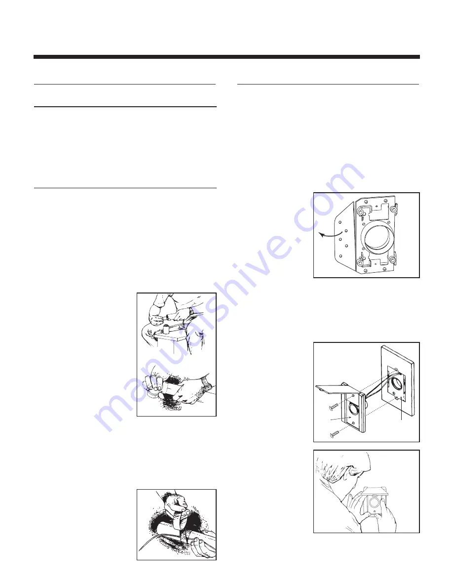
Remove the nail flange
from the inlet mounting
plate (
Fig. 1
). Apply cement
to both the inside of the
flexible tubing and to the
outside of the mounting
plate’s tube ring. Insert
the mounting plate’s
tube ring in the flexible
tubing and twisting the
pieces as you join them to spread the cement, and align the
mounting plate in a vertical position.
Now, strip the ends of the two low-voltage wires, and then
connect the wires to the screw terminals on the back of the
inlet cover. When the wiring is complete, assemble the inlet
cover to the tube guard and mounting plate.
COMPLETING
THE INLET
ASSEMBLY
Once you have attached
the mounting plate to the
flexible tubing, pull the
low-voltage wire through
the top wiring hole in the
mounting plate.
INSTALLING
THE INLET
Place the inlet into the
wall cutout (the inlet
cover remains on the
outside). Hold the inlet in
place and gradually
tighten down each screw
a little bit at a time.
For more details on inlet installation, visit www.broan.ca
for the Central Vacuum System Installation Instructions.
GENERAL INFORMATION
WALL INLET INSTALLATION
AR0040
INLET
MOUNTING
PLATE
AE0024A
AO0045
F
IG
. 1
AO0010
AO0011


