background image

16

8-Button Wall Plate Ethernet Keypad User Manual (LB-KP8E-ICP / LB-KP16E-ICP)

  CONFIGURATION

THE BACKGROUND 

LIGHT BAR ALLOWS 

USER TO INSTANT-

LY CHANGE THE 

LEDS LIGHTING 

PERCENTAGE 

BASED ON THE 

ORIGNIAL ILLUMI-

CLICK ON KEY SET-

TINGS TO CONFIG-

URE THE REPEAT 

OR TOGGLE SET-

TING OF A KEY. IF 

REPEAT IS SET TO 

ON, PRESSING AND 

HOLDING THE KEY 

Key Settings

Click on Key Settings to configure the repeat or toggle setting of a key. If Repeat is set 

to On, pressing and holding the key causes the programmed macro to be repeated. 

If Toggle is set to On, pressing the key the first time executes the macro for that key. 

Pressing the key a second time executes the extension macro for the corresponding 

key. Note: Key 17 is the corresponding toggle key for Key 1.

Содержание LB-KP16E-ICP

Страница 1: ...erves the right to make changes to the products described herein without prior notice or consent No liability is assumed as a result of their use or application All rights reserved 2019 Broadata Commu...

Страница 2: ...OBSERVE THE FOLLOWING SAFETY PRECAUTIONS SURGE PROTECTION DEVICE RECOMMENDED This product contains sensitive electrical components that may be damaged by electrical spikes surges electric shock lightn...

Страница 3: ...t your dealer In case liquid spillage on device unplug mains power cord and contact your dealer Continu ous use in this case may result in fire or electric shock To reduce the risk of electric shock d...

Страница 4: ...DUCT DESCRIPTION OPERATION CONTROL AND FUNCTIONS FRONT REAR PANEL TELNET COMMANDS CONFIGURATION SPECIFICATIONS MAINTENANCE AND TROUBLESHOOTING SERVICE PROCEDURE REPLACEMENT POLICY RETURN AND REPAIR SE...

Страница 5: ...capability to remotely power the wall plate over Ethernet Each button is easily custom labeled to identify the button s function Features include 1 gang wall plate Ethernet keypad with 8 buttons LB K...

Страница 6: ...d in Section 2 5 Relay Out Connect with device that supports DC 0 24V 5A power or signal that sup ports relay function Control Connect from PC Laptop with active internet service or Telnet or WebGUI c...

Страница 7: ...MMAND LIST NONE HELP N SHOW DESCRIP OF COMMAND N COMMAND NAME RELAY N N1 RELAY CONTROL N PORT 1 N1 OPEN CLOSE TOGGLE LEDBLUE N N1 LED BLUE BACKLIGHT CONTROL N LEN NO 1 8 N1 1 100 LEDRED N N1 LED RED B...

Страница 8: ...u and type cmd in the Search field then press enter Under Windows XP go to the Start menu and click on Run type cmd with then press enter Once in the command line interface CLI type telnet then the IP...

Страница 9: ...a PC Laptop that is connected to an active network system open a web browser and type device s IP address on the web address entry bar A security page will appear to ask for User and Password please...

Страница 10: ...strate the function of lighting LEDs Macro 1 Light up the Red backlight LED with 100 brightness sequentially from 1 8 with every 500ms Macro 2 Light up the Blue backlight LED with 100 brightness seque...

Страница 11: ...8E ICP LB KP16E ICP 11 CONFIGURATION KGROUND R ALLOWS O INSTANT ANGE THE LIGHTING RCENTAGE ED ON THE AL ILLUMI Click on the edit symbol to edit command settings Up down arrows are to move the command...

Страница 12: ...elay devices connected through the Relay outputs of Wall Plate Control Box with delay time It is suggested the delay time is 100ms once the setting is confirmed double click on Save Change Command set...

Страница 13: ...URATION KGROUND R ALLOWS O INSTANT ANGE THE LIGHTING RCENTAGE ED ON THE AL ILLUMI Command set to control the Relay devices require to set the Port number Click on Save Change to confirm the setting Ex...

Страница 14: ...s to insert new commands or delete commands A maximum of 128 commands are supported each command is less than 128 characters including spaces Alternatively up to 32 commands each command greater than...

Страница 15: ...P 15 CONFIGURATION KGROUND R ALLOWS O INSTANT ANGE THE LIGHTING RCENTAGE ED ON THE AL ILLUMI Device Settings Click on Device Settings to setup the IP Address of a device Click on Edit to add a new dev...

Страница 16: ...ON PRESSING AND HOLDING THE KEY Key Settings Click on Key Settings to configure the repeat or toggle setting of a key If Repeat is set to On pressing and holding the key causes the programmed macro t...

Страница 17: ...E AL ILLUMI Schedule Click on Schedule to set the executing time schedule of the Macro s Note The scheduling system supports up to 48hrs of memory under power blackout after that the system will reset...

Страница 18: ...ate Ethernet Keypad User Manual LB KP8E ICP LB KP16E ICP CONFIGURATION THE BACK LIGHT BAR USER TO LY CHA LEDS PER BASE ORIGNIA Click on Edit from Once column to set the macro command s to be activated...

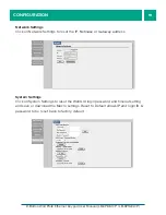
Страница 19: ...RCENTAGE ED ON THE AL ILLUMI Network Settings Click on Network Settings to reset the IP Netmask or Gateway address System Settings Click on System Settings to reset the WebGUI login password and timeo...

Страница 20: ...CHA LEDS PER BASE ORIGNIA Time Settings Click on Time Settings to set the system time and to enable disable Daylight Saving Time DST function Simply click on the white column and a calendar will appea...

Страница 21: ...switch 3 Plug one end of a CAT5 canle into the LAN1 or LAN2 port on the LBC H O R ICP Plug the other end of the CAT5 cable into any available port of the Ethernet Switch 4 Connect the Receiver LBC H O...

Страница 22: ...go to the top menu bar Click on Configure and then click on System The Configure System page will be shown In the System panel make sure that the Keypad Type selected is 8 button keypad BUTTON CON FI...

Страница 23: ...ct LB KP8E and click on the Next button Record the IP address shown in the IP Address box Go back to the LBC H O R ICP Configure System page and enter the LB KP8E ICP s IP address in the Network Keypa...

Страница 24: ...ON On the top menu bar click on Customize and then click on 8 16 Button Keypad The following Button Keypad Definition page will be loaded On the top menu bar click on Keypad The virtual 8 button keypa...

Страница 25: ...e assigned to a button An action can be a native control type such as Relay Video Control or Audio Control or an external control type such as RS 232 IR or Telnet Standard button configuration example...

Страница 26: ...button F2 to turn off Relay 1 1 In the Edit Button drop down menu select F2 2 Type in Relay 1 Off in the Label field 3 In the Mode drop down menu select Standard 4 In the Action Number drop down menu...

Страница 27: ...RCENTAGE ED ON THE AL ILLUMI To test the buttons click on Keypad on the top menu bar The following keypad should be shown Click on the Relay 1 On button to turn on Relay 1 Click on the Relay 1 Off but...

Страница 28: ...state turns on Relay 2 and the Release state turns off Relay 2 1 In the Edit Button drop down menu select F3 2 In the Label field type in Relay 2 3 In the Mode drop down menu select Toggle 4 In the A...

Страница 29: ...10 In the Action Upon drop down menu select Release 11 In the Action Number drop down menu select Action 1 12 In Spacing field enter 0 0 13 In the Action Type drop down menu select Relay 14 In the Act...

Страница 30: ...button should return to white release state Standard button configuration example RS 232 action The following configuration sets button F4 to transmit an RS 232 serial string This configuration requi...

Страница 31: ...lick on Customize and then click on 8 16 Button keypad 1 In the Edit Button drop down menu select F4 2 Type in RS 232 String in the Label field 3 In the Mode drop down menu select Standard 4 In the Ac...

Страница 32: ...following keypad should be shown Click on the RS 232 String button to transmit the string serial string on RS 232 channel 1 On the LB KP8 pressing the F4 button should also transmit the string serial...

Страница 33: ...B KP8E ICP Operating Temperature 0 to 40 C operating Storage Temperature 20 C to 60 C Power Supply 5V 2 6A CERTIFICATIONS FCC CE GREEN COMPLIANCE RoHS ORDER INFORMATION LB KP16E ICP LinkBridge 16 Butt...

Страница 34: ...ubleshooting procedures 1 If the POWER indicator is OFF check for the following a The line cord is plugged into the unit and your outlet has power 2 If the POWER indicator is ON but the Link indicator...

Страница 35: ...no user serviceable components If you have a problem with your unit please contact the Customer Service Department To facilitate our return repair processing please contact Broadata Communications In...

Страница 36: ...tions or failure resulting from misuse abuse neglect alterations electrical power problems usage not in accordance with product instructions improper installation or damage determined by BCI to have b...

Страница 37: ...ata Communications Inc 2545 West 237th Street Suite K Torrance CA 90505 1 800 214 0222 310 530 1416 310 530 5958 Facsimile e mail Sales Broadatacom com Website www broadatacom com 2545 West 237th Stre...

Отзывы: