background image

28

5HQRYHQW([FHOOHQW)

Chapter 11    Electric connections accessories

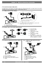
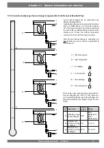
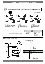
&RQQHFWLRQH[DPSOHVPXOWLSOHVZLWFK

Wire colours C1 - C6 may vary dependent on 
the type of modular cable used.

1RWH )RUWKHPRGXODUFDEOHXVHWKH³WDE´RIERWKPRGXODUFRQQHFWRUVPXVWEH

mounted facing the mark on the modular cable.

A   = Renovent Excellent
B   = Receiver for wireless 
  remote 

control 

C  =  Transmitter with 4 settings
  (e.g. 

kitchen)

D  =  Transmitter with 2 settings
  (e.g. 

bathroom)

E  =  Any additional 2- or 4-settings trans-

mitters (A maximum of 6 transmit-
ters can be signed on to 1 receiver)

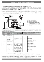
A     =  Renovent  Excellent
B1 =  Multiple switch with 

¿

lter indication

B2 =  Additional multiple switch with 

¿

lter indication

C     =  Splitter

A   =  Renovent Excellent
B   =  Multiple switch with 

¿

lter indication

C   =  Receiver for wireless remote control
D   =  Transmitter with 2 settings
E   =  Splitter

A multiple switch can be connected to the modular connector X2 of the Renovent Excellent. This modular connector X2 is directly 

DFFHVVLEOHDWWKHUHDURIWKHGLVSOD\FRYHUVHH†ZLWKRXWKDYLQJWRWDNHLWRႇ

230 V
50 Hz

230 V
50 Hz

230 V
50 Hz

230 V
50 Hz

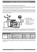
0XOWLSOHVZLWFKZLWK¿OWHULQGLFDWLRQ

A = Renovent Excellent
B = Multiple switch with 

¿

lter indication

:LUHOHVVUHPRWHFRQWUROZLWKRXW¿OWHULQGLFDWLRQ

$GGLWLRQDOPXOWLSOHVZLWFKZLWK¿OWHULQGLFDWLRQ

11.2.4  Additional multiple switch with wireless 
 

remote control

Содержание Renovent Excellent 450

Страница 1: ...Renovent Excellent 450 Plus WWW BRINKAIRFORLIFE NL 614784 F INSTALLATION INSTRUCTIONS English ...

Страница 2: ......

Страница 3: ...ceived clear instructions on the safe use of the appliance and understand the possible dangers on the condition that the appliance has been placed and installed in the normal position for use Children between the ages of 3 and 8 may not insert the plug into the socket nor clean or make changes to the settings o fthe appliance nor carry out any maintenance on the appliance that would normally becar...

Страница 4: ... Factory setting Fault Trouble shooting Display codes 1 1 2 5 6 6 7 7 7 8 9 9 9 9 9 10 10 10 10 10 12 12 12 12 13 13 14 14 14 15 16 17 18 19 19 20 20 20 21 21 21 Table of contents 9 9 1 9 2 10 10 1 11 11 1 11 2 11 2 1 11 2 2 11 2 3 11 2 4 11 3 11 4 11 5 11 6 11 7 11 8 12 12 1 12 2 13 14 Maintenance Filter cleaning Maintenance Electric diagrams Basic diagram Electric connections accessories Connect...

Страница 5: ...nit Renovent Excellent includes the following components c Heat recovery appliance type Renovent Excellent d Wall mounting bracket kit containing VXVSHQVLRQ VWULSV SURWHFWLYH FDSV UXEEHU VWULS UXEEHU ULQJV PRXQWLQJ LQVWUXFWLRQV e PVC condensate discharge connection containing V QWKHWLF VFUHZ JODQG VHDOLQJ ULQJ 39 JOXHG FRXSOLQJ PP f Documentation set consisting VKRUW PDQXDO 1 1 Scope of delivery 1...

Страница 6: ...ss remote control for battery version 532172 Kit wireless remote control 2 positions 1 transmitter 1 receiver 532173 Kit wireless remote control 4 positions 1 transmitter 1 receiver 532174 ZD VZLWFK ZKLWH ÀXVK PRXQWHG ZLWKRXW OWHU LQGLFDWLRQ Delivered with insert plate and cover frame 540214 ZD VZLWFK ZLWK OWHU LQGLFDWLRQ ÀXVK PRXQWHG PRGXODU FRQQHFWLRQ Delivered with insert plate and cover frame ...

Страница 7: ...y Article description Article code LOWHU NLW 62 H30 OWHU SFV 531771 Filterset 1x ISO Coarse 45 G3 1x ISO ePM 1 50 F7 2 stuks 531773 RH sensor 310657 Mounting support Excellent 450 217035 Enthalpie heat exchanger 532059 Servicetool 531961 ...

Страница 8: ... 5HQRYHQW FHOOHQW ...

Страница 9: ...board which increases the connection options These installation instruction describe both the standard Reno vent Excellent and the Renovent Excellent Plus The Renovent Excellent Plus is available in the left handed RU ULJKW KDQGHG YHUVLRQ OHIW KDQGHG YHUVLRQ KDV WKH OWHUV RQ WKH OHIW EHKLQG WKH OWHU GRRU D ULJKW KDQGHG YHUVLRQ KDV WKH OWHUV RQ WKH ULJKW EHKLQG WKH OWHUHG GRRU 7KH SRVLWLRQ RI WKH D...

Страница 10: ...64 Duct diameter mm Ø180 External diameter condensate discharge mm Ø32 Weight kg 38 Filter class ISO Coarse 45 G3 ISO ePM 1 50 F7 optional for supply Fan setting factory setting 1 2 3 Ventilation capacity m3 h 50 100 200 300 Permissible resistance ducts system Pa 2 5 5 15 20 60 40 130 Rated power excl preheater W 9 5 11 18 32 45 80 105 Rated current excl preheater A 0 10 0 10 0 18 0 30 0 46 0 70 0...

Страница 11: ...0 Right handed 4 0 1 To dwelling 2 To atmosphere 3 From dwelling 4 From atmosphere 5 Electric connections 6 Connection condensate discharge 7 Wall mounting bracket note the correct position of the rubber strip washers and caps Renovent Excellent 450 left handed 4 0 Mounting wall suspension kit 7 10 mm ...

Страница 12: ... temperature 10 Indoor temperature sensor Measures the dwelling air temperature 11 Condensate discharge Connection condensate discharge Kit comes separately with the appliance 12 Extract fan Discharges air from the dwelling to the atmosphere 13 Supply fan Feeds fresh air into the dwelling 14 Modular connector multiple switch X2 RQQHFWLRQV IRU FDEOH WR PXOWLSOH VZLWFK LI GHVLUHG ZLWK OWHU LQGLFDWRU...

Страница 13: ...d at 24 C Bypass valve closed The outdoor temperature is lower than 7 C or the outdoor temperature is higher than de indoor temperature in the dwelling or the temperature outside the dwelling is lower than the temperature set at step no 5 in the settings menu minus the set temperature on the hysteresis step no 6 this temperature is standard set at 22 C 24 0 C minus 2 0 C 5HQRYHQW FHOOHQW 3OXV YHUV...

Страница 14: ...ning WKH OWHUV DQG FDUU LQJ RXW PDLQWHQDQFH 0DNH VXUH WKHUH LV D IUHH VSDFH RI DW OHDVW FP DERYH WKH display cover so it can always be removed 5 4 Connecting ducts The air ducts must be mounted air tight 7KH DLU H WUDFW GXFW GRHV QRW KDYH WR EH WWHG ZLWK D FRQWURO YDOYH 7KH DSSOLDQFH LWVHOI FRQWUROV WKH DLU ÀRZ UDWHV A duct diameter of 180 mm is required for the Renovent Excel lent 450 To prevent ...

Страница 15: ... OLPLWHG WR P V LQ WKH PDLQ GXFWV and 3 5 m s in the branches 7KH ORFDWLRQ RI WKH PHFKDQLFDO YHQWLODWLRQ RXWSXW DQG WKH sewer stack vent relative must be chosen to prevent nui sance KRRVH WKH ORFDWLRQ RI WKH VXSSO YDOYHV WR SUHYHQW IRXOLQJ and draught We recommend to use the Brink supply valves KHQ PRXQWLQJ ÀH LEOH GXFWV EHDU LQ PLQG WKDW LW PXVW EH possible to replace them in due course KHQ PRXQW...

Страница 16: ...tch to setting 3 for longer than 2 seconds or by switching it to absence mode 5 5 1 Connecting the power plug The appliance can be connected to an easily accessible earthed wall socket with the plug that is mounted to the ap pliance The electric installation must comply with the require ments of your power company Make allowance for the 1000 W preheater Warning The fans and control board carry a h...

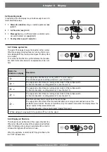
Страница 17: ...splay will show the operating mode see 6 2 IWHU RSHUDWLQJ WKH NH µ0HQX WKH NH V RU FDQ EH XVHG WR VHOHFW IURP WKUHH GLႇHUHQW PHQXV LQFOXGLQJ Settings menu SET see 6 3 Readout menu READ see 6 4 Service menu SERV see 6 5 Press the R key to leave any menu and return to operating mode ULHÀ SUHVV WKH 5 NH VKRUWHU WKDQ VHFRQGV WR VZLWFK RQ the display backlight without changing anything in the menu Key ...

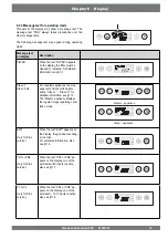
Страница 18: ...to the table below for an explanation of the num bers Status fan situation on display Description The supply and extrad fans are running at 50 m3 h or are inactive 1 This situation depends on setting parameter 1 see Chapter 13 1 The supply and extract fans are running under mode 1 of the multiple switch LU ÀRZ UDWH GHSHQGV RQ VHWWLQJ SDUDPHWHU VHH FKDSWHU 2 The supply and extract fans are running ...

Страница 19: ...For coupled appliances the mes sage text shelves which appli DQFHV 6ODYH 6ODYH IRU detailed information see 11 3 7KH 0DVWHU DSSOLDQFH GLVSOD V the regular image regarding venti lation mode EWT only for Plus version KHQ WKH WH W 7 DSSHDUV RQ the display the geo heat exchang er is active For extensive information also see 11 6 CN1 or CN2 only for Plus version KHQ WKH WH W 1 RU 1 DS pears on the disp...

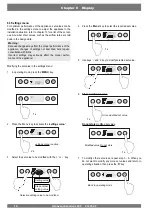
Страница 20: ...LUHG VHW YDOXH 5 Use keys and key to modify selected set value 6 Store PRGL HG VHW YDOXH Do not store PRGL HG VHW YDOXH 7 To modify other set values repeat step 3 6 When you do not want to modify any more set values and return to operating situation then press the R key Warning HFDXVH FKDQJHV PD DႇHFW WKH SURSHU SHUIRUPDQFH RI WKH appliance changes of settings not described here require consultati...

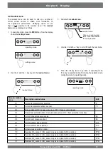
Страница 21: ...ription readout value Unit 01 Current temperature from dwelling C 02 Current temperature outdoors sensor o C 03 Bypass status ON bypass valve open OFF bypass valve closed 04 Status frost protection ON frost protection active OFF frost protection not active 05 Current channel pressure supply Pa 06 Current duct pressure extract Pa 07 XUUHQW DLU ÀRZ UDWH VXSSO IDQ m3 h 08 XUUHQW DLU ÀRZ UDWH H WUDFW ...

Страница 22: ...go to the service menu 3 Activate the service menu 4 Use the and the key to scroll through the messages in the service menu Display not any fault message Current fault message spanner on display Unsolved fault message no spanner on display 5 Press the R key twice to go back to operating mode If no key is operated during 5 minutes the appliance auto matically returns to operating mode OO IDXOW PHVV...

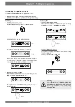
Страница 23: ...nt will be running in the mode is set on the multiple switch If no multiple switch is connected the appliance will always run in mode 1 Switching on through software KHQ WKH 5HQRYHQW FHOOHQW VZLWFKHG Rႇ WKURXJK VRIW ZDUH WKH GLVSOD ZLOO VKRZ WKH WH W 2 The appliance can be switched on by pressing the key during 5 seconds Chapter 7 Putting into operation 6ZLWFKLQJ WKH DSSOLDQFH RQ DQG Rႇ Warning Wh...

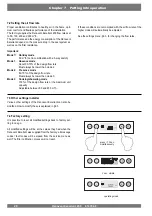
Страница 24: ...an mode 3 Mode 3 Cooking showering mode RI WKH GHVLJQ ÀRZ UDWH RU WKH PD LPXP XQLW capacity GMXVWDEOH EHWZHHQ DQG P3 h I WKHVH FRQGLWLRQV DUH QRW FRPSOLHG ZLWK WKH DLU ÀRZ UDWH RI WKH KLJKHU PRGH ZLOO DXWRPDWLFDOO EH DGMXVWHG 6HH WKH VHWWLQJV PHQX IRU FKDQJLQJ WKH ÀRZ UDWHV Chapter 7 Putting into operation 7 4 Factory setting W LV SRVVLEOH WR UHVHW DOO PRGL HG VHWWLQJV EDFN WR IDFWRU VHW ting in o...

Страница 25: ...nce check the pressure hose connections Fault E999 If when the appliance is powered up directly to message E999 appears on the display the mounted control board is not suit able for this appliance or the dip switches on the control board are set incorrectly For the location of the dip switches see 10 1 In that case check whether the dip switches on the control board are set as shown in the drawing...

Страница 26: ...XOW will automatically be reset Check cabling E106 locking fault The temperature sensor that measures the outdoor tem perature is defective RWK IDQV DUH VZLWFKHG Rႇ 3UHKHDWHU V LV VZLWFKHG Rႇ Bypass closes and is blocked Take the voltage from the appliance Replace temperature sensor Put voltage back on appliance fault will automatically be reset E107 non locking fault The temperature sensor that m...

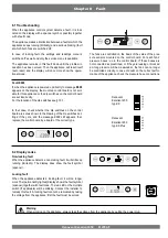
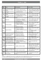
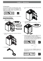
Страница 27: ...DW ZD WKH OWHUV DUH taken out OHDQ WKH OWHUV 3ODFH WKH OWHUV EDFN WKH VDPH ZD DV WKH ZHUH WDNHQ out ORVH WKH OWHU GRRU Switch on the appliance by pressing the key during 5 seconds IWHU WKH OWHUV KDYH EHHQ FOHDQHG RU UHSODFHG SUHVV WKH R NH IRU VHFRQGV WR UHVHW WKH OWHU LQGLFDWLRQ The text FILTER ZLOO EOLQN EULHÀ WR FRQ UP WKDW WKH OWHUV have been reset Also when the message FILTER KDV QRW HW DSSHD...

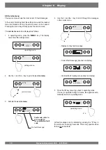
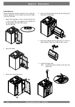
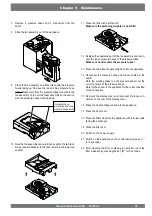
Страница 28: ...RU VHFRQGV WKH DSSOLDQFH ZLOO EH VZLWFKHG Rႇ WKURXJK VRIWZDUH DQG VZLWFK Rႇ WKH SRZHU 2SHQ WKH OWHU GRRU 5HPRYH WKH OWHUV 3 Remove the move the front cover 4 Remove the heat exchanger Be careful not to damage the foam parts in the appliance 5 Rinse the exchanger with hot water max 45 ºC and a regular detergent Rinse the exchanger with hot water 7DNH Rႇ WKH GLVSOD FRYHU 1RWH LUVW GLVFRQQHFW WKH FRQ...

Страница 29: ...oses to the pressure tubes 0DNH VXUH QR GLUW HQWHUV WKH SUHVVXUH WXEHV 13 Place the complete fan assembly back into the appliance 14 Reconnect the pressure hoses and the fan cables to the board Note the marking sticker on the pressure sensor for the correct position of the pressure hoses Refer to the sticker in the appliance for the correct position of the connectors 15 Remount the display cover a...

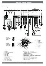
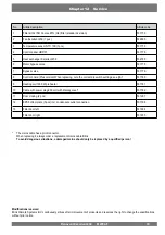
Страница 30: ...sitive application depending on parameter setting 8 P Postheater Plus version Q Output 0 or 10 V Plus version R Sensor postheater or outdoor sensor geo heat exchanger Plus version S 24 volt connector Plus version T Input 0 10 V or make contact Plus version U Make contact or input 0 10 V Plus version Z RH sensor option C1 brown C2 blue C3 green yellow C5 white C6 wire no 1 C7 wire no 2 C10 yellow C...

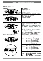
Страница 31: ...ter temperature sensor must also be con nected to X15 7 and X15 8 For the Plus version use the additionally mounted pull relief in the display cover to feed the 230 V cable to the postheater Connector X15 only for Plus version Chapter 11 Electric connections accessories Connector X15 SROH for connecting special versions Connection Application 1 2 input 1 Stepnr 15 0 normally open contact factory s...

Страница 32: ...xcellent B1 Multiple switch with lter indication B2 Additional multiple switch with lter indication C Splitter A Renovent Excellent B Multiple switch with lter indication C Receiver for wireless remote control D Transmitter with 2 settings E Splitter A multiple switch can be connected to the modular connector X2 of the Renovent Excellent This modular connector X2 is directly DFFHVVLEOH DW WKH UHDU...

Страница 33: ...ntilation PRGH Ƒ Important Because of polarity sensitivity always connect contacts X1 1 to X1 1 and contacts X1 2 to X1 2 Never connect X1 1 and X1 2 230V 50Hz 230V 50Hz 230V 50Hz For C2 Slave2 Set parameter 9 to 2 Slave 2 Display always shows ventilation PRGH Ƒ Step nr Description Factory setting Range 8 Communica tion type eBus 0t Opentherm eBus 9 eBus address 0 0 master 1 9 slave 1 9 RQQHFWLRQ ...

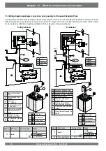
Страница 34: ... LED maximum safety lights up when acti vated F Cables to be con nected by installer G Flow direction through the heater C1 brown C2 blue C3 green yellow C4 black Step nr Description Factory setting Range 13 Heater 0 2ႇ 1 Preheater 2 Postheater I To dwelling II To atmosphere III From dwelling IV From atmosphere A Renovent Excellent Plus B Control board Plus version C Heating coil max 1000 W D Temp...

Страница 35: ... geo heat exchanger is connected it is not possible any more to connect a postheater to WKH 5HQRYHQW When using a geo heat exchanger parameter 27 PXVW EH FKDQJHG IURP 2 WR 21 KHQ WKH air is routed through the geo heat exchanger the Renovent Excellent Plus display shows the text 7 Step no Description Factory setting Range 27 Switching on geo heat exchanger OFF ON Switched on OFF 6ZLWFKHG Rႇ 28 Mini...

Страница 36: ... VKRZV WKH WH W 1 1 Bypass conditions opening valve outdoor temperature is higher than 10 C temperature from atmosphere is at least lower than temperature from dwelling temperature from dwelling is higher than the preset bypass temperature parameter 5 A Renovent Excellent Plus B Plus version control board C Contact connected to switch input 1 for instance a switch or a relay contact D Display Reno...

Страница 37: ...d C Provision connected to 0 10 V input for instance a humidity sensor or a CO2 sensor Connected provision has its own power supply D Display Renovent Excellent Plus text V2 appears when the provi sion is active on input 2 If connection X15 1 and X15 2 are programmed as second 0 10 V input parameters 15 16 and 17 can be used to modify the various situations the same as for the standard 0 10 V inpu...

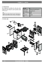
Страница 38: ...e the serial number the year of production and the name of the part N B Appliance type serial number and year of production are VWDWHG RQ WKH LGHQWL FDWLRQ SODWH RQ WKH WRS RI WKH DSSOLDQFH 12 2 Service parts DPSOH Appliance type Renovent Excellent 450 4 0 R Serial number 420200212801 Year of production 2021 Part Fan Article code 532605 4W 1 10 7 1 4 5 2 13 3 6 3 9 8 12 11 12 12 ...

Страница 39: ...l 1000 W preheater 531781 10 Cable with power plug 230 volt with display cover 531782 11 Door closing 2 pcs 531297 12 EPS bottom plate 3 pcs incl condensate outlet connection 531798 13 Filter door left 531934 Filter door right 531935 The mains cable has a print connector When replacing it always order a replacement mains cable Brink 7R DYRLG GDQJHURXV VLWXDWLRQV D GDPDJHG PDLQV VKRXOG RQO EH UHSOD...

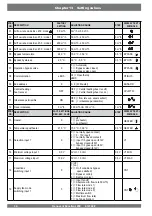
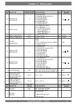
Страница 40: ...mbalance permissible ON OFF ÀRZ UDWH VXS HTXDOV H WUDFW ON imbalance permissible 12 Fixed imbalance 0 m3 h 100 m3 h t m 100 m3 h 1 m3 h STEP NO DESCRIPTION FACT SETTINGS REN EXC PLUS ADJUSTING RANGE STEP DISPLAY TEXT SYMBOLS 13 Heater 0 Rႇ 1 preheater 2 postheater HEATER 14 Temperature postheater 21 0 C 15 0 C 30 0 C 0 5 C HEATER 15 Selection input 1 0 0 normally open contact 1 0 10V input 2 norma...

Страница 41: ...fan mode switching input 2 5 0 QSXW IDQ Rႇ 1 EVROXWH PLQ ÀRZ UDWH P3 h 2 Flow rate mode 1 3 Flow rate mode 2 4 Flow rate mode 3 5 Multiple switch 6 0D LPXP ÀRZ UDWH 7 No input fan activation CN2 26 Extract fan mode switching input 2 5 0 WUDFW IDQ Rႇ 1 EVROXWH PLQ ÀRZ UDWH P3 h 2 Flow rate mode 1 3 Flow rate mode 2 4 Flow rate mode 3 5 Multiple switch 6 0D LPXP ÀRZ UDWH 7 No extract fan activation ...

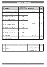
Страница 42: ...Bus CO2 sensor 2 400 39 Max PPM eBus CO2 sensor 2 1200 40 Min PPM eBus CO2 sensor 3 400 41 Max PPM eBus CO2 sensor 3 1200 42 Min PPM eBus CO2 sensor 4 400 43 Max PPM eBus CO2 sensor 4 1200 44 Flow correction 100 90 110 45 Default position switch 1 0 1 Chapter 13 Setting values STEP NO DESCRIPTION FACTORY SETTING ADJUSTING RANGE STEP 46 Brink Connect 1 1 Brink Connect function ex tern Brink Connect...

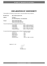
Страница 43: ...ility of the manufacturer Manufacturers Brink Climate Systems B V Address 3 2 R 1 6WDSKRUVW The Netherlands Product 5HQRYHQW FHOOHQW 5HQRYHQW FHOOHQW Plus The product described above complies with following directives Ɣ 8 2 8 Ɣ 8 2 8 Ɣ 8 2 8 Ɣ 8 2 8 Ɣ 5R 6 8 2 8 The product described above has been tested according to the following standards Ɣ 1 Ɣ 1 Ɣ 1 Ɣ 1 Ɣ 1 Ɣ 1 Staphorst 11 10 21 ...

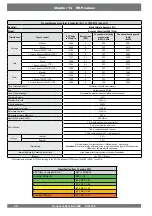
Страница 44: ... of heat exchanger 5HFXSHUDWLYH SODVWLF FURVV FRXQWHUÀRZ KHDWH FKDQJHU 7KHUPDO HႈFLHQF 84 0D LPXP ÀRZ UDWH 450 m h Electric power input 222 W Sound power level Lwa 51 dB A 5HIHUHQFH ÀRZ UDWH 315 m h 5HIHUHQFH SUHVVXUH GLႇHUHQFH 50 Pa 6SHFL F 3RZHU QSXW 6 0 28 Wh m Control factor 1 0 in combination with manual switch 0 95 in combination with clock 0 85 in combination with 1 sensor 0 65 in combinati...

Страница 45: ......
Страница 46: ...ORLIFE NL 614784 F October 2021 P O Box 11 NL 7950 AA Staphorst The Netherlands Wethouder Wassebaliestraat 8 NL 7951 SN Staphorst The Netherlands T 31 0 522 46 99 44 F 31 0 522 46 94 00 info brinkclimatesystems nl www brinkclimatesystems nl ...

Отзывы: