26
5HQRYHQW([FHOOHQW)
X4
X1
X6
Chapter 10 Electric diagrams
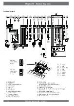
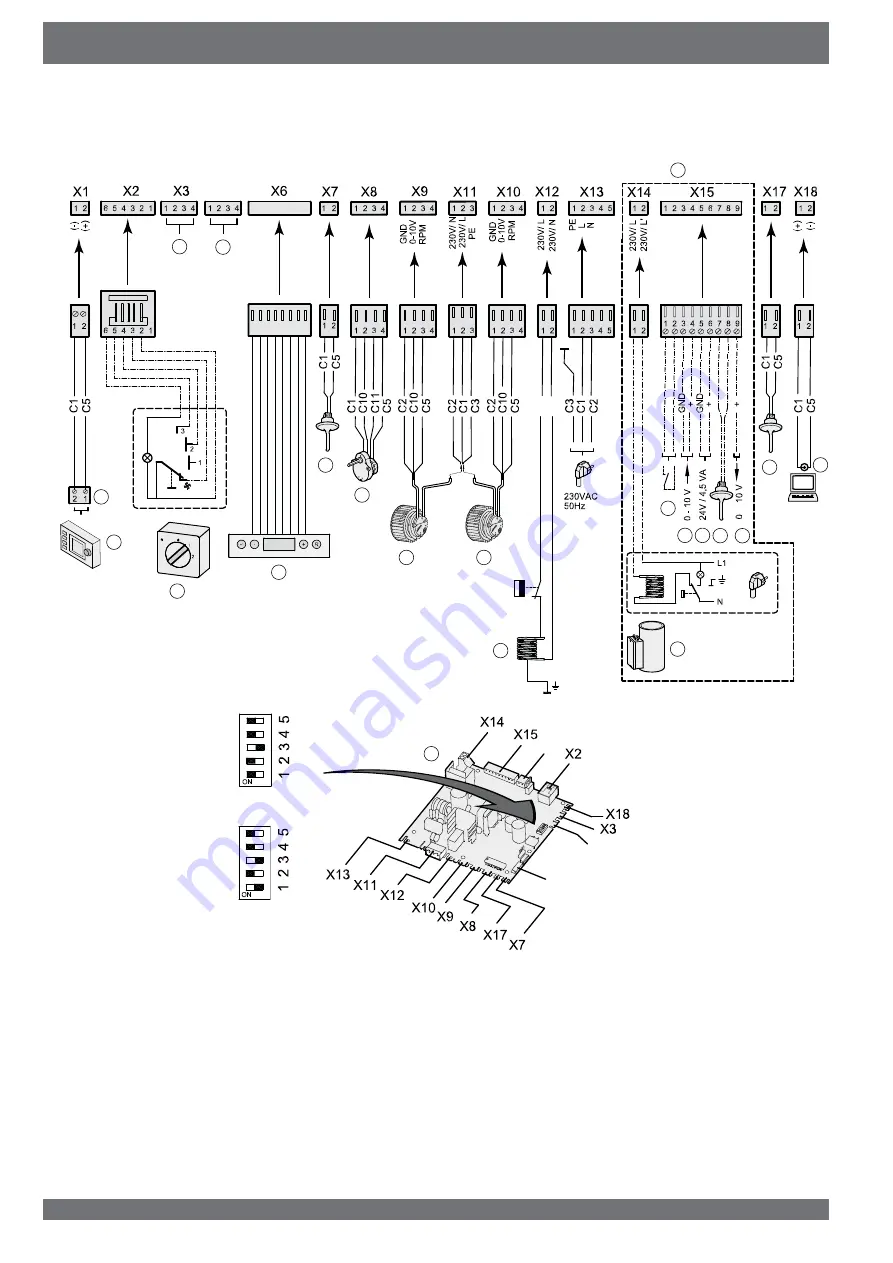
10.1 Basic diagram
A = Multiple switch
B = Preheater
C = Outdoor temperature sensor
D = Control board
E = Supply fan
F = Extract fan
G = Control panel
H = Indoor temperature sensor
J = Service connector
K = Valve motor bypass
L = Renovent Plus version
M = Brink Air control (option)
N = Not applicable
O = E bus connector (polarity sensitive),
application depending on parameter setting 8
P = Postheater (Plus version)
Q = Output 0 or 10 V(Plus version)
R = Sensor postheater or outdoor sensor geo heat exchanger
(Plus
version)
S = 24 volt connector (Plus version)
T = Input 0-10 V (or make contact) (Plus version)
U = Make contact or input 0-10 V)(Plus version)
Z = RH-sensor (option)
C1 = brown
C2 = blue
C3 = green/yellow
C5 = white
C6 = wire no.1
C7 = wire no.2
C10 = yellow
C11 = green
X4
3
C6
C7
1 2 3 4 5 6 7 8
1 2 3 4 5 6 7 8
or
A
T
F
E
C
L
B
M
G
H
K
R
4
P
O
U
D
Z
N
S
J
Renovent
Excellent 450
typ 4/0
Renovent
Excellent 450
typ 4/0 Plus
Содержание Renovent Excellent 450
Страница 1: ...Renovent Excellent 450 Plus WWW BRINKAIRFORLIFE NL 614784 F INSTALLATION INSTRUCTIONS English ...
Страница 2: ......
Страница 8: ... 5HQRYHQW FHOOHQW ...
Страница 45: ......


