background image

Page 39

Page 38

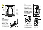
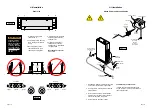
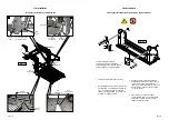
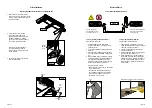
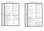
Maintenance and Lubrication Schedule

1500 

Cycles

Resecure or replace if needed.      

Replace damaged parts and resecure 

as needed.  Apply Light Oil.

Resecure, replace or correct as needed.  

Apply light oil.

Resecure, replace or correct as needed.

Correct, replace damaged parts and/or 

relubricate.

Inspect external snap rings: 

•  Platform slide/rotate pivot pins (2 per  

   pin)

•  Platform fold axles (1 per axle)

•  Bridge plate lever bracket pins (1 per 

pin)

•  Lift-Tite

 latch gas (dampening) 

spring (2 per spring)

•  Roll stop clevis pins (1 per pin) 

•  Roll stop foot pins (2)

•  Platform pivot pins (2)

Inspect inner fold arm pins (2), axles (2) 

and bearings (8) for wear or damage 

and positive securement

Inspect turnbuckle assemblies for 

wear or damage, proper operation and 

positive securement

Remove pump module cover and 

inspect:

•  Hydraulic hoses, fittings and 

connections for wear or leaks 

•  Harness cables, wires, terminals 

and connections for securement or 

damage

•  Relays, fuses, circuit breaker, and 

power switch for securement or 

damage

Inspect Lift-Tite

 latch rollers for wear 

or damage, positive securement and 

proper operation (2)

Resecure, replace or correct as needed

Use BraunAbility 32840-QT hydraulic 

fluid (Exxon

®

 Univis HVI 26).  Do not 

mix with Dextron III or other hydraulic 

fluids.  Check fluid level with platform 

lowered fully.  Fill to maximum fluid 

level indicated on reservoir (specified 

on decal).  Do not overfill.  If fluid level 

decal is not present - measure 35 mm 

from the fill port to locate fluid level.

Tighten, repair or replace if 

needed. 

Inspect cotter pins on platform pivot 

pins (2)

Hydraulic Fluid (Pump) - Check level.  

Notice:  Fluid should be changed if 

there is visible contamination.  Inspect 

the hydraulic system (cylinder, hoses, 

fittings, seals, etc.) for leaks if fluid level 

is low.

Inspect cylinders, fittings and hydraulic 

connections for wear, damage or leaks

4500 

Cycles

Maintenance and Lubrication Schedule

Replace if needed. 

Tighten or replace if needed.

Replace damaged parts and resecure 

as needed.  Apply Light Grease during 

reassembly procedures.

Replace if needed.

Tighten, replace or correct as 

needed 

Apply Door-Ease or replace if needed.  

See Lubrication Diagram.


Resecure or replace if needed.     

Resecure, repair or replace if needed.

Check to see that the lift is securely 

anchored to the vehicle and there are 

no loose bolts, broken welds, or stress 

fractures.

Replace decals if worn, missing or 

illegible.  Replace antiskid if worn or 

missing.  

Inspect parallel arms, bearings and 

pivot pins for visible wear or damage

Inspect parallel arm pivot pin mounting 

bolts (8)

Inspect platform pivot pin, bearings and 

vertical arms for wear, damage and 

positive securement

Inspect inner/outer fold arms, saddle, 

saddle support and associated pivot 

pins, bushings, and bearings for visible 

wear or damage

Inspect gas springs (cylinders) for 

wear or damage, proper operation and 

positive securement

Inspect saddle bearings (2) buttons (4) 

Inspect vertical arm plastic 

covers       

Inspect power cable 


Mounting 


Decals and Antiskid

4500 

Cycles

Repeat all previously listed inspection, 

lubrication and maintenance procedures at 

750 cycle intervals.

Consecutive 

750 Cycle 

Intervals

Содержание Vista 2

Страница 1: ...2014 Original Instructions International Public Use Wheelchair Lifts Owner Manual ISO 9001 2008 www braunability com international 631 West 11th Street Winamac IN 46996 USA Phone 1 574 946 6153 Fax 1 574 946 4670 Split Platform ...

Страница 2: ...freedom for years Thank you again for your business and enjoy your independence Sincerely The BraunAbility Employee Family XXXXXXXXXX INDIANA USA The Braun Corporation MFG DATE XX XXXXX SERIAL NUMBER MODEL NUMBER XX XX XXXX OWNER S WARRANTY REGISTRATION War Card 07 ai PURCHASED FROM DATE INSTALLED NAME ADDRESS CITY TELEPHONE TO VALIDATE WARRANTY REGISTRATION CARDS MUST BE RETURNED TO THE BRAUN COR...

Страница 3: ...latform Half Stabilizer Roller Installation and Adjustment 19 Roll Stop Anti Rattle Installation and Adjustment 20 Tower Microswitch Adjustment 21 22 Installer Verification 23 24 Lift Operation Safety 25 27 Lift Operating Instructions 28 30 Manual Operating Instructions 31 32 Emergency Stop E Stop Operating Instruction 33 Maintenance and Lubrication Schedule 34 40 Declarations Declaration of Confo...

Страница 4: ...when working with flammable materials to prevent injury or damage This symbol indicates a device weighs in excess of 139kg 306 lbs Use of a fork lift or hoist is required NOTICE Route all cables clear of exhaust system other hot areas moving parts wet areas etc Risk of electrical shock or fire Use extra care when making electrical connections Connect and secure as outlined in Installation Instruct...

Страница 5: ...e presence of high pressure hydraulic hoses Use appropriate personal protective equipment when working on hydraulic system WARNING Lift Operation Safety Keep operator and bystanders clear of area in which the lift operates Lift attendant must observe passenger at all times during lift operation Ensure adequate lighting exists in the lift operating area Whenever a wheelchair passenger or standee is...

Страница 6: ...g or riding on the platform Open lift door s fully and secure before operating lift Position and secure buckle engage fasten etc the wheelchair equipped occupant seat belt torso restraint before loading onto the wheelchair lift platform Lift attendants must ensure that lift occupants keep hands arms and all other body parts within the lift occupant area and clear of moving parts Platform must be p...

Страница 7: ... VL996IB3042 2 63 15 63 15 63 15 54 34 57 83 59 32 70 75 44 70 22 07 22 07 22 07 15 12 Notice X must be measured from opposite pump side as shown X Y Rear Front Outboard passenger s side Inboard driver s side Arrows 30 30 6 13 90 of vehicle of vehicle Outboard Right Left Inboard UP DOWN 32819 FOLD UNFOL D 32820 Pump Module Hand Held Pendant Control Base Plate Top Parallel Arm 2 Adjustable Quiet Ri...

Страница 8: ...A l i g n B a s e P l a t e w i t h D o o r O p e n i n g D O O R O P E N I N G Alignment Side to Side Alignment See Figure B on previous page The lift vertical arms and platform should be perpendicular 90 to the vehicle floor and parallel aligned with the ver tical sides of door jamb The vertical arms and the parallel arms must clear the door opening when the lift folds and unfolds Inboard to Out...

Страница 9: ...OOSEN TIGHTEN Loosen Tighten Tighten Tighten Loosen Loosen Figure H Lift Installation Dimensions MUST be Equal 90 90 32879 005 ai To Correct To Correct TIGHTEN LOOSEN LOOSEN LOOSEN TIGHTEN TIGHTEN LOOSEN TIGHTEN Floor Grommet Rubber Boot Star Washer 3 8 Hex Nut Power Feed Stud 1 Drill 28 5mm diameter grommet access hole Check under the vehicle for obstructions 2 Insert grommet Secure grommet with ...

Страница 10: ...or male plug is supplied To meet minimum CE requirements connect to vehicle interlock harness as outlined below Steps 1 5 INTERLOCK CONNECTOR P21 6 5 4 3 2 1 SIGNAL DEFINITION NO 9 COND WIRE CODE 7 8 9 VEHICLE SECURE 12V INPUT LIFT NOT STOWED GND NOT AVAILABLE NOT AVAILABLE NOT AVAILABLE NOT AVAILABLE NOT USED NOT USED LIFT STOWED GND 4 6 5 1 3 2 7 9 8 1 3 2 4 6 5 7 9 8 T o I n t e r l o c k Disco...

Страница 11: ...nbuckle Note Loosen jam nut to adjust turnbuckle length Tighten jam nut after adjustment Shorten Turnbuckle Lengthen Turnbuckle Jam Nut Figure 1 Figure B Lowering Sequence Requirements 1 The outboard end toe of the platform must contact the ground first to ensure the spring loaded outer barrier unfolds fully See Figure B 2 The inboard end heel of the platform must lower fully turn buckle brackets ...

Страница 12: ... 2 to mounting brackets Item 1 as indicated using 5 16 18 X 2 1 4 carriage bolt Item 9 roller axle Item 8 lock washer Item 3 and 5 16 hex nut Item 4 Tighten securely 3 Position and mount bracket and bumper assemblies to lift towers as shown Secure to lift using 5 16 18 X 3 4 carriage bolt Item 5 1 4 flat washer Item 6 5 16 lock washer Item 7 and 5 16 acorn nut Item 10 Snug tighten 4 Stow lift full...

Страница 13: ...ckwise 3 full turns 3 Press pendant UP switch continue press ing switch until platform stops 4 When platform stops turn switch adjust ment screw clockwise while pressing the pendant UP switch Platform position will change Adjust platform to meet criteria listed for Tower 1 Switch Proper Adjust ment Criteria TOWER 1 TOWER 2 31130 TOWER 3 TOWER 4 31131 TOWER 2 TOWER 1 32942 TOWER 4 TOWER 3 32943 Fig...

Страница 14: ...erclockwise 1 8 turn 7 Press UP switch and verify platform does not lift tilt is permissible 8 If platform does not lift tighten 9 16 hex nut do not turn relief valve adjustment screw while tightening hex nut If platform does lift repeat steps 6 through 8 Review adjustment procedures below and adjust as needed only Left rear pump lift depicted Right front pump lift is a mirrored image Tower 3 Coun...

Страница 15: ...minor person al injury or property damage B This symbol indicates important safety in formation regarding a potentially hazardous situation that could re sult in serious bodily injury and or property damage D Additional information provided to help clarify or detail a specific subject The information contained in this manual and supplements if included is provided for your use and safety Familiari...

Страница 16: ... operate lift if you suspect lift damage wear or any abnormal condition Do not use as a link bridge WARNING WARNING WARNING WARNING If the lift operating instructions manual operating instructions and or lift operation safety precautions are not fully understood contact BraunAbility immediately Failure to do so may result in serious bodily injury and or property dam age WARNING WARNING WARNING WAR...

Страница 17: ...horizon tal position Control Switch Functions Hand held Pendant Control The hand held attendant s pendant control is equipped with two rocker switches When there is power to the lift the lift function labels illuminate to identify the functions FOLD From floor level the FOLD function folds the platform inward to the stowed position UNFOLD From stowed position the UNFOLD function unfolds the platfo...

Страница 18: ...UP fully verti cal see Photo I and raise the platform to floor level See Photo J Release switch 3 Unlock wheelchair brakes and unload passenger from platform TO FOLD PLATFORM Press FOLD In switch un til platform stops fully folded See Photos K and L Release switch CLOSE DOOR S Notice Bridge plate and roll stop automatically function during manual operations B Hand Pump Handle Release Valve maximum...

Страница 19: ...roll stop unfolds See Photo C Down To Lower Using hand pump handle a Place slotted end of pump handle onto release valve and turn clockwise to close securely See Photo C Notice Valve must be tight but do not overtighten b Insert handle into back up pump and stroke until platform reaches floor level see Photo D To Fold Platform In Insert handle in pump and stroke until plat form stops folds fully S...

Страница 20: ... at the recommended intervals inspection and lubrication procedures specified in the previous sections should be repeated These intervals are a general guideline for sched uling maintenance procedures and will vary ac cording to lift use and conditions Lifts exposed to severe conditions weather environment contami nation heavy usage etc may require inspection and maintenance procedures to be perfo...

Страница 21: ...Apply Light Oil See Lubrication Diagram Correct as needed Correct as needed See service manual 750 Cycles Apply grease synthetic to contact areas between upper lower fold arms See Lubrication Diagram Apply Light Oil See Lubrication Diagram Apply Light Oil See Lubrication Diagram Apply Light Oil See Lubrication Diagram Apply Light Oil See Lubrication Diagram Apply Light Oil See Lubrication Diagram ...

Страница 22: ...locate fluid level Tighten repair or replace if needed Inspect cotter pins on platform pivot pins 2 Hydraulic Fluid Pump Check level Notice Fluid should be changed if there is visible contamination Inspect the hydraulic system cylinder hoses fittings seals etc for leaks if fluid level is low Inspect cylinders fittings and hydraulic connections for wear damage or leaks 4500 Cycles Maintenance and L...

Страница 23: ... newer Lifts Manufacturer BraunAbility 631 West 11th Street Winamac IN 46996 USA Authorized Representative Specifications with which Conformity is Declared Essential Health and Safety Requirements of Annex 1 of the Machinery Directive We hereby certify that the machinery described above conforms with the essential health and safety requirements of Council Directive 2006 42 EC on the approximation ...

Страница 24: ...required Factors that influence the actual level of exposure of the workforce include characteristics of the work room the other sources of noise etc such as the number of machines and other adjacent processes Also the permissible level of exposure can vary from country to country This information however will enable the user of the machine to make a better evaluation of the hazard and risk Operat...

Страница 25: ...l All illustrations descriptions and specifications in this manual are based on the latest product information available at the time of publication The Braun Corporation reserves the right to make changes at any time without notice Original Instructions Vista 2 International Public Use Wheelchair Lifts Owner Manual Split Platform Patent 5 261 779 Patent 6 065 924 Patent 6 238 169 Patent 6 464 447 ...

Отзывы: