33
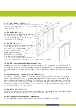
9. THE FLAP CONTROL BUTTON
(fig.2/9)
The white button is used to open and close the clear plastic upper
and lower page-holding flaps. This is necessary when mounting
and dismounting a book.
10. THE GREEN LED
(fig.2/10)
The green light emitting diode lights up only when
the TURNY is in the „flipping backwards“
mode. Thus, when the green LED is lit, the pages
are transported from left to right.
11. THE RED LED
(fig.2/11)
The red light emitting diode has many functions.
Foremost it indicates that the power is on.
When turning on the TURNY it blinks
four times and then remains
steady, indicating normal use.
Each touch of the bellow, blow
in the tube, or other controll signal
causes the red LED to blink validation. The red LED is
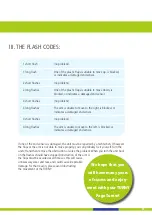
also used to convey the error codes (described later in this manuel, see part F.III)
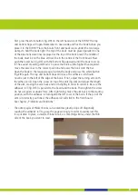
12. THE END SENSOR AND THE MAGNETIC PIN
(fig.2/12)
At the end of the turning arm is the end sensor with the magnetic pin. The end sensor is the most delicate part of
the TURNY. It is through the end sensor that the software can define the postion of the page turning mechanism of
the TURNY. Neither the end sensor nor the magnetic pin may be mechanically influnced. Do not touch the magnetic
pin.
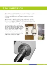
13. DIE ADHESIVE ROLL AND THE TENSION-SCREW
(fig.2/13)
The sticky roll is to be attached below the end sensor. In order to remove or replace a roll, loosen the associated
tension screw, paying attention that the cog teeth point upwards along the small metal pin. The numbers make it
easier to find an unused portion of the adhesive roll. After affixing a new roll, retighten the tension screw. Differing
types of paper require different strengths of adhesion. For example, high-gloss papers require much less adhesion
than recycling-quality. A reduction of adhesion can be assertained by rolling the roll between the fingers; when it
rolls easily, the stickyness is no longer adequate.
14. THE SLITS FOR CLIPS
(fig.2/14)
These slits are for mounting the clips used to accomodate wider books and magazines. The narrow side of the clips
fit into the slot, allowing the wider side to move freely and hold the book or magazine.
15. THE GUIDE SLOTS FOR THE BOOK SUPPORT BAR
The pins of the book support bar fit into the guide slots in order to hold the bar level. (fig.2/15)


