


30
B. SET-UP figur 1
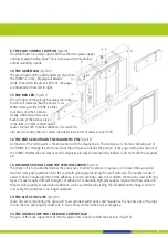
I. CONNECTORS AND BASIC FUNCTIONAL ELEMENTS (fig.1)
1. THE BLOW-TUBE
The blow-tube is optional equipment for controlling the TURNY. The blow-tube is constructed of individual,
solid links. This stiff, yet flexible segmented tube is available in almost every possible length. The
advantage to the segmented tube is that is holds its position. The connection for the blow-tube must be
pre-installed by the factory because it replaces the mini-jack. (fig.1/1)
2. THE 3.5 MM MINI-JACK
The 3.5-mm mini-jack is for attaching any other (short-circuit type) switch to control the TURNY. The minijack
conforms to the mono-jack-standards. (fig.1/2)
3. THE POWER SWITCH
The power switch turns the TURNY on and off. Be careful only to turn the TURNY in „forward-mode“ off;
otherwise you run the risk of damaging the TURNY. Always turn the power switch off (0) before
connecting or disconnecting any of the cables! (fig.1/3)
4. THE POWER SUPPLY PLUG
First make sure that the power switch (fig.1/3) on the left hand edge is in the OFF position (zero pressed
inwards). The power lead has a three-pin plug which must be connected to the far left jack on the
connector board on the back side of the TURNY (fig.1/4). Hold back the small ring of the plug and then fit
the plug into the connector. Rotate the plug carefully until it fits easily into the connector. Tighten the
mounting ring. Now you can plug the power supply into a 110V power source.
5. THE TURNING-ARM PLUG
At the end of the page-turning-arm is a wire which ends in a five-pin-plug. This wire controls the magnetic
lock of the black pin, located above the adhesive roll at the end of the arm. Connect the plug to the
second, middle connector (fig.1/5).
6. THE BOOK-SUPPORT-BAR
The wire from the book support bar ends in a four-pin-plug and controls the moveable plastic flaps that
help to hold the pages in place. Fit the plug to the far right connector (fig.1/6), tightning the mounting ring to
secure the plug.
7. THE BLOW TUBE CONNECTOR
This small plastic tube connects the internal air pressure switch to the blow tube. This tube can also be
replaced with the bellow. A small funnel into which the user can blow to control the TURNY can also be
attached here, although it is important when using the funnel to have the sensitivity set very high (see next
paragraph). (fig.1/7)


