31
8. THE AIR PRESSURE SWITCH
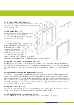
The air pressure switch is regulated by either the bellow, the blow tube, or a small funnel. Any one of these is
connected to the TURNY by pressing the attached rubber tube (fig.1/7) to the black connector of the air pressu-
re switch (fig.1/8). Make sure that the tube is not bent, squeezed or clampt such that the air flow is restricted.
Inside the case and above of the air pressure switch is a small screw for adjusting the sensitivity (fig.1/8).
When using the bellow there will be no need to adjust the unit; if the blow tube or the funnel is to be used, you
will need to change the sensitivity. To open the TURNY unscrew the two screws, holding the back cover plate.
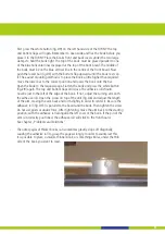
Now the aluminium plate is exposed on which the connectors and the air pressure switch are mounted. The
plate is fixed with two long screws and washers to the main bar. Unscrew the left screw a little and the right
screw completely. Now you can sufficiently move the plate to expose the red screw above the pressure switch.
For greater sensitivity turn the screw clockwise. Normally a quarter turn clockwise will suffice. Do not over-
tighten the screws when replacing the aluminium plate. This may cause damage to the threads.
9. THE BELLOWS TUBE
Attach the rubber tube for the bellow to the black connector of the air pressure switch (fig.1/8).
10. THE POWER SUPPLY
The power supply provides the TURNY with 12 Volt AC. (fig.1/10)
11. THE BELLOW
The bellow is used to controll the TURNY. (fig.1/11)


