background image


MANUAL P/N 900000108 REV D 

40

5.1.6


Help 

 
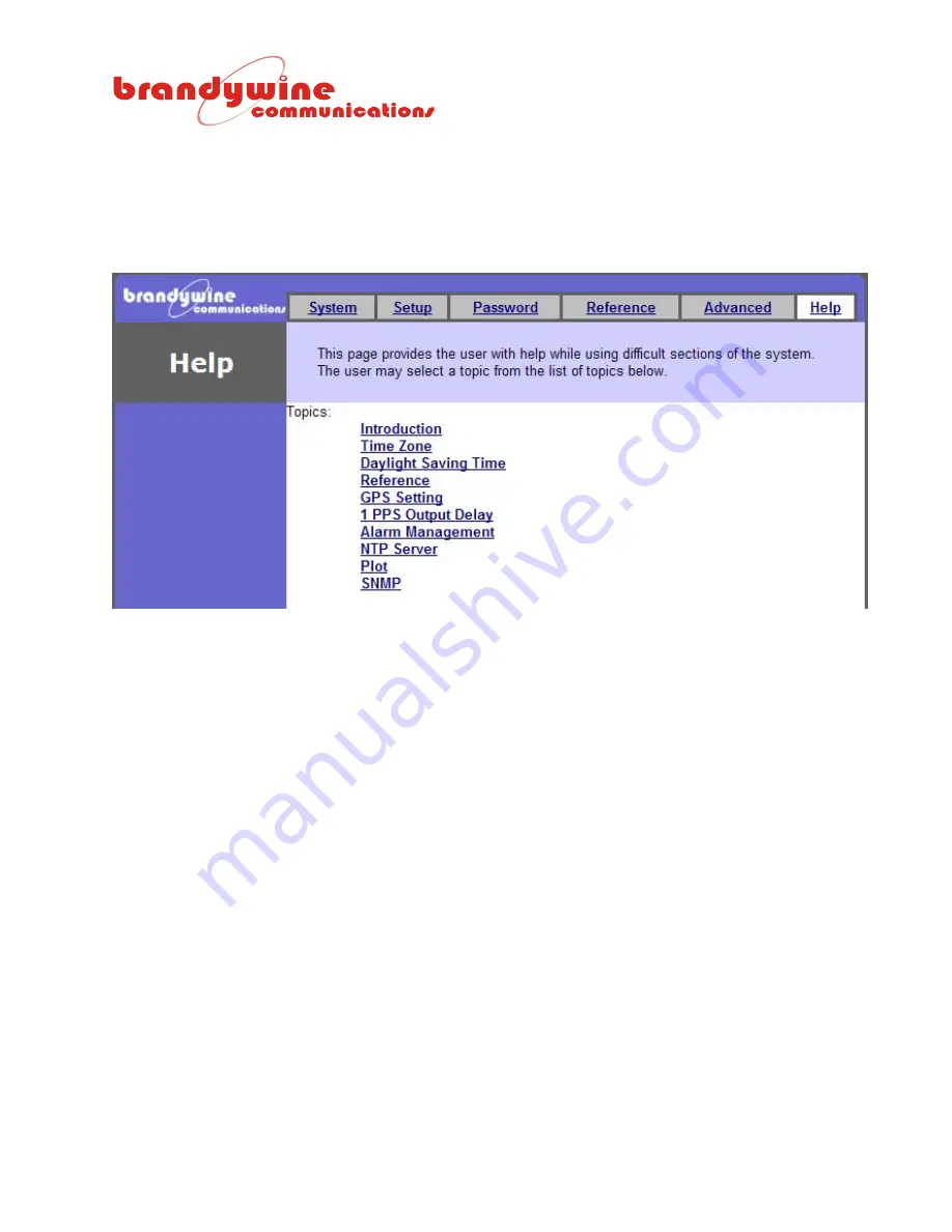
The Help tab provides the user with help while using difficult areas in the system.  Help links are 

located throughout the entire system so the user has access to the Help screen whenever the user 
encounters a problem.  Once the user clicks on the Help link the user will be automatically redirected to 

the Help screen.  Various topics are discussed in the Help screen. 


Figure 18 Help Screen 


Содержание 023000004

Страница 1: ...000108 REV D User Guide Enhanced Network Time Appliance Model ENTA 2 P N 023000004 Revision D August 2011 Brandywine Communications 1153 Warner Ave Tustin CA 92780 714 755 1050 714 755 0175 http www brandywinecomm com ...

Страница 2: ... Initial Release 2 JUL 2009 Updated Screen Shots Text A JUL 2009 QA updates B AUG 2009 Updated IRIG B input and 10MHz output connector numbers in table 1 C AUG 2009 Added UL requirements Updated Telnet information and FPGA install D AUG 2011 Changed Title Page Updated FPGA Upload ...

Страница 3: ...k to people CAUTION The exclamation point inside of an equilateral triangle is intended to alert the user to the presence of important operation and maintenance instructions in the user guide WARNING Rack Mount Instructions The following instructions shall be followed with the installation of the unit Elevated Operating Ambient If installed in a closed or multi unit rack assembly the operating amb...

Страница 4: ...on should be given to the connection of the equipment to the supply circuit and the effect that overloading of the circuits might have on over current protection and supply wiring Reliable Earthing Reliable earthing of rack mounted equipment should be maintained Particular attention should be given to supply connections other than direct connections to the J1 Connector WARNING J1 output is not a L...

Страница 5: ...lay 8 1 8 Environmental 8 1 9 Mechanical 9 1 10 Rear Panel Connections 10 2 General Description 11 3 Unpacking and Installation 12 3 1 Unpacking 12 3 2 Installation 12 3 3 Connections 12 3 3 1 Power 12 3 3 2 Antenna 12 3 3 3 Network Connection 14 3 3 4 Other Connections 14 4 Getting Started 15 4 1 Powering Up the ENTA 15 4 2 Setting the Network Address 15 4 2 1 IPSetup exe 16 4 2 2 Web Browser 17 ...

Страница 6: ...face 41 5 2 2 TCP 2500 Socket Interface Command List 41 5 3 TELNET and Console Port Configurations 42 5 3 1 Opening TELNET Session 42 6 Uploading Firmware 44 7 Uploading FPGA 46 7 1 FPGA Update 46 7 2 FPGA Upload 49 8 Maintenance and Troubleshooting 51 9 Drawings 52 ...

Страница 7: ...25 m SEP Site Survey mode 5 m SEP typical after position average Datum WGS 84 1 2 Internal Oscillator 1 2 1 Oscillator Type GPS disciplined High Precision OCXO Aging 5x10 10per month when free running Temperature coefficient 2x10 9 20 C to 50 C Design lifetime 20 years 1 3 Inputs 1 3 1 Antenna Type Active patch antenna Connector BNC Pre amp power 5 VDC 80 mA via center conductor 1 3 2 1 PPS Signal...

Страница 8: ...se width 10 microseconds On time Rising edge Phase relationship to 10 MHz When synchronized there are always 107 10 MHz cycles between each 1 PPS rising edge 1 5 Network Ports Number of ports 2 Port type Ethernet 10 100BaseT Protocols supported NTP RFC 1305 Telnet RFC 854 Connector RJ 45 1 6 Status Indicators LEDS Power Green Indicates power is available Fault Red Indicates monitored parameter is ...

Страница 9: ...V D Connector IEC 320 with integrated switch and fuse Fuse 1A 5x20mm slo blo EMC FCC port 15 EN55022 EN55024 1 9 Mechanical Size unit 17 x 1 72 x 9 excluding the connectors and handles Front panel width 19 Weight 5 lbs nominal ...

Страница 10: ...2 J6 DB 9 MALE NOT USED PORT 3 RS232 J7 DB 9 MALE NOT USED PORT 4 RS232 J8 DB 9 MALE NOT USED IRIG B IN J10 BNC CENTER IRIG B SHIELD GROUND 10MHz OUT J9 BNC CENTER 10 MHz SHIELD GROUND 1 PPS IN J11 BNC CENTER 1 PPS SHIELD GROUND 1 PPS OUT J12 BNC CENTER 1 PPS SHIELD GROUND 1 IRIG E DC LEVEL SHIFT J13 BNC CENTER IRIG E TIME CODE SHIELD GROUND 1 IRIG E OUT J14 BNC CENTER IRIG E TIME CODE SHIELD GROU...

Страница 11: ...EV D 11 2 General Description GPS Micro processor IRIG Generator IRIG Reader OCXO DDS DIV MOD MOD 10MHz 1PPS IRIG B IRIG B DC IRIG E IRIG E DC MAC PHY 10 100 10 100 ANTENNA IRIG B 1 PPS Figure 1 ENTA Simplified Block Diagram ...

Страница 12: ... power cord into the rear of the power entry module and connect the power cord to an AC power outlet 3 3 2 Antenna Connect the GPS antenna to the Antenna connector J3 on the rear panel of the ENTA The GPS antenna must be placed in a suitable location with a clear view of the sky In most cases the GPS signals do NOT penetrate buildings Use the provided antenna cable to connect the GPS antenna to th...

Страница 13: ...ky For these cases pick the location with the best view of the sky Exposure to High RF Fields Some antenna installations may occur in locations where a variety of high power transmitters and antennas are located The GPS antenna should not be directly exposed to or bombarded with high level RF energy In such cases it is better to place the antenna either above below or to the side of high power RF ...

Страница 14: ...s The ENTA is shipped with 100 of high quality antenna cable which has a loss of approximately 13 dB Refer to Table 2 for additional cable configurations For distances beyond 330 an in line amplifier is required PART NUMBER CABLE LENGTH CABLE TYPE 002 0037 100 ft RG 58 supplied 002 0039 330 ft RG 8 002 0040 150 ft RG 8 051000001 In line amplifier 20 dB TNC TNC connectors Table 2 Antenna Cables 3 3...

Страница 15: ...inated green within 2 seconds The POWER LED indicates that the ENTA has power Once the GPS has acquired satellites time should be displayed on the front panel in the format HH MM SS 4 2 Setting the Network Address The ENTA is shipped with a label that indicates the IP address stored in the unit The default settings are IP Address 192 168 1 240 Subnet Mask 255 255 255 0 Gateway 192 168 1 1 To set t...

Страница 16: ... Network Mask GateWay and DNS 6 To transfer the NDK Settings to the selected ENTA unit click the button 7 Wait 15 seconds for the NDK Settings to be loaded into the ENTA unit and for the ENTA unit to restart 8 Verify that the ENTA unit has the correct NDK Settings and is connected to the network by clicking the Search Again button 9 To exit the IP Setup program click the Close button 10 Open a web...

Страница 17: ...nnect the other end of the Ethernet cable to your network 3 Open a web browser type the IP Address of the ENTA unit in the Address bar and press Enter For example type 192 168 1 240 or http 192 168 1 240 and press Enter 4 Figure 3 will be displayed 5 Configure the ENTA unit For more information on ENTA configuration refer to the Configuration section of the user guide Figure 3 ENTA System Screen ...

Страница 18: ...itor the ENTA via a web browser based interface Java software must be installed on your computer To obtain the Java software follow the steps given below 1 Go to http www sun com 2 Click on the Downloads link 3 Click on the Java Download link 4 Download Java 5 Complete the installation process ...

Страница 19: ... Via the web browser recommended Via a TELNET session Via the console port 5 1 Web Browser Configuration 5 1 1 System The System tab consists of two sections the System Status and Reference Status This tab allows the user to view the state status and reference of the ENTA system Figure 4 ENTA System Screen ...

Страница 20: ...IRE The system is acquiring its reference LOCKED The system is locked to its reference HOLDOVER The system is in holdover Table 3 System States 5 1 1 2 Reference Status The Reference Status section consists of two fields the Reference Type and Locked The Reference Type refers to the reference the system is acquiring time from If the reference is locked and provided to the disciplining engine Locke...

Страница 21: ...MANUAL P N 900000108 REV D 21 Figure 5 Setup Screen ...

Страница 22: ...ease note that once the IP address is changed using the web browser the user must enter the new IP address in the address bar of the web browser to continue monitoring the ENTA If an IP address is entered that is not reachable from the computer running the web browser it will not be possible to refresh the ENTA web browser based interface 5 1 2 3 Front Panel Display The Brightness box is available...

Страница 23: ...ylight saving start time the occurrence of the specific day the day of the week and the month that the daylight saving should start For example Pacific Standard Time adds an hour at 02 00 on the second Sunday of March The Daylight Savings Time End allows the user to subtract the DSTO from the time the daylight saving should stop The user must enter the daylight saving stop time the occurrence of t...

Страница 24: ...et button IMPORTANT INFORMATION The default user name and password for the system are both BRANDYWINE The user must always enter a user name and password when submitting changes to the system Figure 6 Password Screen 5 1 3 1 Password The Password consists of four fields the New User Name Old Password New Password and Confirm New Password The new password must be less than 31 characters and cannot ...

Страница 25: ...two sections the Reference and Reference Settings This tab allows the user to select the reference view the reference status and modify the reference settings for the system To save all modifications made to the Reference screen click the Submit button Figure 7 Reference Screen ...

Страница 26: ... Reference There are no external references being used GPS Uses an installed GPS receiver to synchronize the internal clocks IRIG B Unit synchronizes to external IRIG B input J9 1 PPS Unit synchronizes to external 1PPS input J11 The time of day must be set manually by the user Table 4 Time References If the system has acquired time from the reference Reference Stable is TRUE Otherwise Reference St...

Страница 27: ...ference setting as well as the Open Satellite Status The following sections describe the links 5 1 4 2 1 Manually Set Time Figure 8 is displayed when the user clicks on the Manually Set Time link The Manually Set Time consists of four fields the Year Month Day and Time Hours Minutes Seconds This link allows the user to set the date and time Please note that setting the time is only valid when in F...

Страница 28: ...k The GPS Settings screen consists of two sections the Settings and Version This screen allows the user to select a position mode set a position cold start and view the version number of the GPS receiver To save all modifications made to the GPS Settings screen click the Submit button Figure 9 GPS Settings Screen ...

Страница 29: ... value and enters position hold mode Only 1 satellite must be tracked during this time Table 5 GPS Position Modes Upon power up the system checks whether the GPS receiver is in position hold mode or position fix mode If in position hold mode the GPS receiver will be placed in navigation mode and a short position average is performed If the averaged value is within the threshold 100 meters the GPS ...

Страница 30: ...cks on the Cold Start link and enters a valid username and password Cold start clears the almanac of the GPS receiver forces the GPS receiver to search for satellites and rebuilds its almanac Figure 11 GPS Cold Start Window 5 1 4 2 2 2 Version The Version consists of one field and refers to the version number of the GPS receiver ...

Страница 31: ... unobstructed view is between 40 and 50 The SVN is the satellite C A code PRN The Status indicates whether the satellite is used or not The lower left section of the screen displays the current latitude longitude altitude and GPS TFOM of the GPS receiver The Position Mode refers to the position mode of the GPS receiver The Tracking refers to the number of tracked satellites The lower right section...

Страница 32: ... modifications made to the 1PPS Output screen click the Submit button To undo all modifications made to the 1PPS Output screen click the Reset button The 1PPS Output consists of two fields the Input PPS and the IRIG Outputs The Input PPS allows the user to set the Input Cable Delay time in nanoseconds Please note that when the default Input PPS delay value is changed the user may restore the defau...

Страница 33: ...ected To save all modifications made to the Alarms screen click the Submit button Figure 14 Alarms Screen The checkboxes will allow each output signal to create an alarm when a fault is detected on its output circuitry These settings are useful when only a subset of the output signals are being used ...

Страница 34: ... button Figure 15 NTP Server Screen 5 1 5 3 1 Leap Indicator Mode The Leap Indicator Mode consists of two radio buttons the Automatic and Manual The Leap Indicator Mode is a two bit code bit 0 and bit 1 which warns of an impending leap second that is inserted or deleted in the last minute of the current day The Automatic radio button automatically sets the leap indicator settings The Manual radio ...

Страница 35: ...ng used Table 6 describes the supported leap indicator settings used DESCRIPTION No warning Last minute has 61 seconds Last minute has 59 seconds Alarm condition clock not synchronized Table 6 Leap Indicator Settings If the leap indicator setting is set to no warning the ENTA automatically warns of an impending leap second only if the internal GPS receiver is used as the synchronizing source ...

Страница 36: ...s the user to modify the vertical and horizontal scale for the cached time difference plot and view the cached time difference and real time time difference plots The cached time difference displays recorded data for up to 168 hours To save all modifications made to the Plot screen click the Submit button To undo all modifications made to the Plot screen click the Reset button Figure 16 Plot Scree...

Страница 37: ...capabilities listed below ENTA status monitoring via SNMP ENTA control via SNMP Figure 17 is displayed when the SNMP sub tab is selected The SNMP consists of three sections the Community Trap Address and MIB This sub tab allows the user to modify the read community write community and trap IP address and download the MIB file used To save all modifications made to the SNMP screen click the Submit ...

Страница 38: ...ress consists of one field the Trap IP The Trap Address allows the user to enter the IP address of the trap Once the trap address is entered it is stored in non volatile memory and will be recalled when the ENTA is powered up Table 8 describes the trap command used by SNMP COMMAND DESCRIPTION Trap Used by devices to report events to NMS Table 8 SNMP Trap Command 5 1 5 5 3 MIB The MIB consists of o...

Страница 39: ...ad Write Output 1PPS Pulse Width ENTAi1ppsPulseOffset 18954 3 1 12 0 Read Write Output 1PPS Offset Adjust ENTAszSystemTimeSetup0 18954 3 1 13 0 Read Write ASCII DST Format Time Zone ENTAszSystemModelName 18954 3 1 50 0 Read only Friendly Model Name ENTAnReferenceSelect 18954 3 1 51 0 Read Write Selects Reference where 0 GPS 1 IRIG B Input ENTAiWriteToNVM 18954 3 1 1000 0 Read Write Saves Settings ...

Страница 40: ... the system Help links are located throughout the entire system so the user has access to the Help screen whenever the user encounters a problem Once the user clicks on the Help link the user will be automatically redirected to the Help screen Various topics are discussed in the Help screen Figure 18 Help Screen ...

Страница 41: ...NET XXX XXX XXX XXX 2500 and press the OK button The XXX XXX XXX XXX is the IP address of the ENTA Figure 19 Run Screen 4 Figure 20 will be displayed The TCP 2500 socket interface has now been successfully opened Figure 20 TCP 2500 Socket Interface 5 2 2 TCP 2500 Socket Interface Command List The commands supported by the TCP 2500 socket interface are also supported by the telnet and console port ...

Страница 42: ...TELNET Session To open a TELNET session follow the given steps below 1 Go to the Start menu 2 Select Run 3 Figure 21 will be displayed Type TELNET XXX XXX XXX XXX and press the OK button The XXX XXX XXX XXX is the IP address of the ENTA Figure 21 Run Screen 4 Figure 22 will be displayed Enter the username press Enter enter the password and press Enter The TELNET session has now been established Fi...

Страница 43: ...larms 1PPS Output No Alarm See Table 11 10 MHz Output No Alarm IRIG B MOD No Alarm IRIG B DCLS No Alarm IRIG E MOD No Alarm IRIG E DCLS No Alarm RESPONSE Warm up Ready Acquire Locked Holdover Table 10 System State RESPONSE Alarm No Alarm Table 11 Alarm Status 5 3 1 4 GETUSERNAME Command Shows the system username 5 3 1 5 SETUSERNAME Command Sets the system username 5 3 1 6 GETPASSWORD Command Shows...

Страница 44: ...ress of the ENTA in the IP address field If the user does not know the IP address press the Find button and Figure 24 will be displayed Locate and click on the IP address of the unit and click the OK button The IP address field will be completed for you If the unit is not on the list click the Search Again button Figure 24 Find NetBurners Screen 3 Enter the path name to the new released file If th...

Страница 45: ...lick the Dismiss button 6 To upload the new firmware click the Update button and Figure 26 will be displayed for a few seconds Figure 26 Programming Screen 7 After Figure 26 automatically closes Figure 27 will be displayed Click the OK button and now the uploading firmware process is completed Figure 27 AutoUpdate Complete Screen ...

Страница 46: ...GA for the ENTA the user will need a software application called FPGA Update provided by Brandywine This needs to be uploaded on the user s computer 7 1 FPGA Update When installing the FPGAUpdate Application this is the initial Welcome screen Click the Next button ...

Страница 47: ... 47 The FPGA Update application will then request the folder to install the application to Keep the existing folder or browse for a new folder on the user s compluter Click Next Confirm by clicking Next to start the installation ...

Страница 48: ...MANUAL P N 900000108 REV D 48 FPGAUpdate will be installed FPGAUpdate is installed Click Close to exit ...

Страница 49: ... Start FPGA Update Provide the IP address of the unit and the file name of the FPGA to be uploaded Make sure that the Compress FPGA Code File box is not checked Click the Upload FPGA button The above will be shown while the file is being uploaded ...

Страница 50: ...D 50 The Unit Version and the Previous FPGA Version will be shown in the above box The new FPGA version will take effect once the unit has restarted Click the Yes button to restart the unit now or the No button to restart later ...

Страница 51: ... is an excessive cable loss 5 There is excessive EMI interference with the antenna 6 The oscillator is not synchronized 7 There is an oscillator failure 1 Wait for 15 minutes 2 The antenna should see 50 of the sky Use the GPS screen to verify which satellites if any are being tracked 3 Replace the antenna 4 Replace the cable with a lower loss cable 5 Check for nearby interfering radiators and move...

Страница 52: ...MANUAL P N 900000108 REV D 52 9 Drawings FIGURE DESCRIPTION 1 ENTA Front Panel 2 ENTA Rear Panel Table 21 ENTA Drawings ...

Страница 53: ...MANUAL P N 900000108 REV D 53 Figure 1 ENTA Front Panel Figure 2 ENTA Rear Panel ...

Отзывы: