DCD-8 User Manual
Page 13
Page 12
DCD-8 User Manual
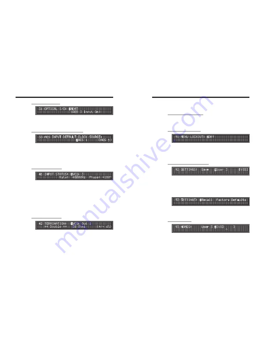
8.11. MENU 31: OPTICAL I/O
Optical I/O can be set to ADAT or S/PDIF Optical.
Note: When Optical I/O is set to S/PDIF Optical instead of ADAT, AES 3 input is
replaced by “Optical” and its front panel BNC input is disconnected.
8.12. MENU 33: AES INPUT DEFAULT CLOCK SOURCE
When any AES or S/PDIF source is used as a reference or as an audio source, it is
automatically used as the default clock source, in that order of priority. If not, the user
can determine in this menu which AES or S/PDIF source to use as the clock source.
This will be used by the DCD-8 primarily for measurements (frequency & phase).
In AUTO mode, the DCD-8 scans through each input and selects the first valid signal it
finds. When no AES inputs are connected, status indicates [Scanning].
8.13. MENU 41: INPUT STATUS
Menu 41 displays the rate and phase of a selected input. The rate of is shown in Hz.
The phase, relative to domain A, is shown in degrees (-180º thru 180º). A positive
value indicates that the source is lagging behind domain A, while a negative value
indicates that it is leading ahead of it.
To view a different input, go to the input field and use the [
up
] and [
down
] keys. Where
there is no information (e.g. nothing plugged in) then both rate and phase fields will
show “n/a”. There is no phase field at all for Video.
The PHASE ERROR LED lights up when the source being observed in menu 41 is out
of phase, which is defined as an error greater than 36º (10%). If the source is drifting,
then the LED will go on and off as the signal goes in and out of phase.
8.14. MENU 42: TERMINATION
This page shows a termination measurement for each of the 8 word clock outputs.
These measurements are not meant to be accurate, but to give an indication.
Ideally, the value displayed should be 75
Ω
. If < 48
Ω
, the word ‘Double’ is displayed;
if < 30
Ω
, ‘Triple’; if >500
Ω
, ‘Open’.
If any output is double or triple-terminated, the
termination
warning LED lights up.
To view a different output, go to the output field and use the [
up
] and [
down
] keys.
NOTE: These are DC measurements. It may not measure AC coupled inputs correctly.
8.15. MENUS 51-59: VIDEO OPTION
Menus 51 to 59 are assigned to the optional Video Sync Generator (VSG-4) and
only appear if this card has been installed. For more info on these menus, see the
VSG-4 manual.
8.16. MENU 91: MENU LOCKOUT
To prevent accidental changes, the DCD-8 menus can be locked out. In this mode,
no changes are permitted.
If a change is attempted while the menus are locked out, an error message appears
on the LCD display: “ERROR - Menus Locked Out.”
8.17. MENU 92: SETTINGS (USER PRESETS)
Menu 92 is used to store and recall user presets. The DCD-8 has provisions to store up
to 4 different presets, labeled USER 0 through USER 3. A name can be associated with
each preset which appears to the right of the display (see Menu 93).
To store a preset, select SAVE. Then select the user preset number you would like to
save to and press [
enter
]. To recall a preset, select RECALL. Then select the user pre-
set number you would like to recall and press [
enter
].
FACTORY DEFAULTS: There is an additional preset holding the Factory Defaults.
This preset can only be recalled and cannot be modified. For details on the Factory
Defaults, see Appendix 6.
8.18. MENU 93: NAMES
Menu 93 lets you define a ‘name’ for each of the 4 user presets. They can be up to 8
characters long. Use the left/right keys to select a character, then use the up/down
keys to edit it. When a text character is being adjusted, there will be a single caret
symbol (^) in the line immediately below it which serves as a cursor. The range of
possible characters in each position is A thru Z, 0 thru 9, dash, period and space.


