DCD-8 User Manual
Page 7
Page 6
DCD-8 User Manual
5. Front Panel Displays & LED’s
The DCD-8 has been designed so that the relevant information would always be avail-
able at a glance on it’s front panel.
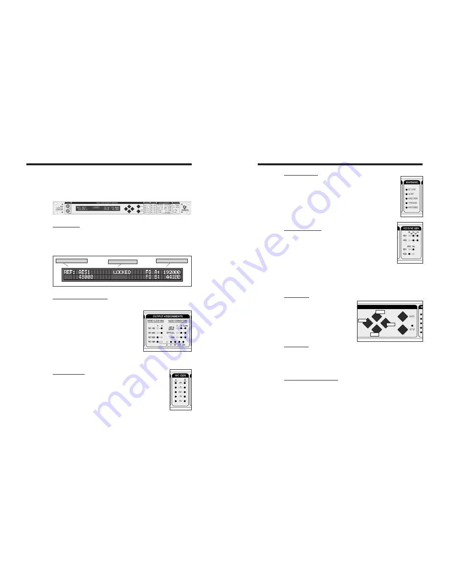
5.1. LCD DISPLAY
The 80 character LCD is broken into three separate areas:
• Left: displays the currently selected reference and it’s frequency
• Center: shows the Lock Status
• Right: displays the selected A & B frequencies.
A & B Frequencies
Selected Reference
Lock Status
5.2. OUTPUT ASSIGNMENTS LED’S
To know what signal has been assigned to each output, there are 22 LED’s describ-
ing the selections made.
Word Clock Outputs: A-B
These LED’s indicate which frequency has been
assigned to each WC output pair: A or B.
For WC Outputs 7&8, 5 LED’s indicate if a multi-
plier has been applied.
Audio Outputs: A-B-Audio
• If ‘Audio’ is off, the output is silent audio at the
A or B rate; LED’s indicate which.
• If ‘Audio’ is on, the output is the audio source selected in menu 6 for A or 7 for B.
5.3. WC GEN LED’S
4 different “pull” coefficients are available. Each has a corre-
sponding LED for A and B domains:
• + 4.16%
• + 0.1%
• - 0.1%
• - 4.0%
These coefficients can be combined to 4.27% and -4.096%.
VSO (varispeed) LED indicates that another rate (non-standard) is generated.
5.4. WARNING LED’S
REF ERROR: a failure of the selected reference occurred
ALT REF: the DCD-8 had to switch to the alternate reference
PHASE ERROR: one of the inputs is out of phase (see menu 41)
TERMINATION: a unit connected to one of the WC outputs is improp-
erly terminated (see menu 42)
B REFERENCE: domain B is not using the same reference as domain A
(see menu 22)
5.5. VIDEO SYNC LED’S
These LED’s are only active if the optional VSG-4 Video Sync
Generator card has been installed in your DCD-8.
For information on these LED’s and the operations of the optional
Video Sync Generator card, please refer to the VSG-4 manual.
6. Navigation Keys
6.1. SET UP KEY
To access the different menus, press the
[
set
up
]
key.
While in Set Up mode, the SET UP LED
is on.
To exit the Set Up mode, simply press
the [
set
up
]
key again.
6.2. ENTER KEY
Scrolling through the different values will not affect anything. Only after the [
enter
]
key
is pressed will a change take place.
When exiting a menu without pressing the [
enter
]
key, the changes are lost.
6.3. UP, DOWN, LEFT, RIGHT KEYS
These keys are directly left of the [
enter
]
and [
set
up
]
keys. They are not labeled as such
because their function is fairly obvious.
While in Set Up mode, the [
up
]
and [
down
]
keys are used to change the value of the
selected field, while the [
left
]
and [
right
]
keys are used to select the different fields.
[
up
]
and [
down
]
keys are also used to change menu pages.
Up
Down
Left
Right


