DCD-8 User Manual
Page 5
Page 4
DCD-8 User Manual
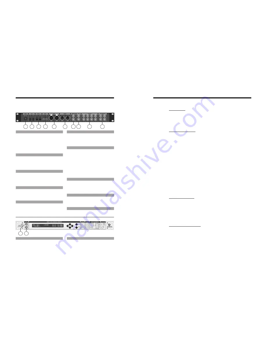
2. I/O’s Description and Cable Requirements
1
2
3
4
5
6
7
8
9
10
3. Installation
3.1. UNPACKING
When unpacking the DCD-8 the following items should be in the shipping carton:
• DCD-8 unit
• Universal Power Supply (12VDC @ 25w)
• IEC power cable
• Owner’s Manual & Registration card
3.2. INSTALLING THE DCD-8
The DCD-8 is designed to be mounted in a standard 19” rack. It requires 1U in height.
Ideally, it should be located near your AD/DA and in the same rack.
Usual precautions should be respected when wiring the DCD-8: use high quality cables with
good shield to guarantee a good signal transmission. Keep your cables as short as possible.
Devices connected to the DCD-8’s WC outputs need to be terminated. If no termination is pro-
vided on the device, use a BNC-T with a 75
Ω
termination. If multiple devices are connected to
a single DCD-8 WC output, only the last device in the chain should be terminated. However,
to preserve the integrity of the transmission line, it is recommended that you do not daisy-
chain word clock outputs as it can significantly degrade signal quality.
4. Quick Start
The DCD-8 is extremely versatile and can accommodate many different situations. You
should read this manual to familiarize yourself with its many features. The following
simple steps are only provided to get you started right away.
Connect the power supply provided with the DCD-8 to the 4 pin DIN power connector on
the rear panel and plug the IEC cable into a proper wall outlet. This turns on your unit.
If the unit has already been used, refer to page 13 to reset the factory settings. If not, out of the
box, the DCD-8 is set to generate a 48KHz Word Clock, referenced to its internal crystal. This
rate is fed to all WC outputs, as well as all audio outputs (as silent audio).
4.1. CHANGING THE RATE
To select a different rate, follow these steps:
• Press the [
set
up
]
key (the
set
up
LED lights up)
• In Menu 01, press the [
right
]
navigation key once to move to the Rate field
• Press the [
up
]
or [
down
]
keys to select the desired rate
• Press the [
enter
]
key to confirm your choice
• Press the [
set
up
]
key again to exit SET UP (the Set Up LED goes out)
Your selection is reflected in the upper right corner of the LCD display, following FQ A.
4.2. CHANGING THE REFERENCE
To select a different reference, follow these steps:
• Press the [
set
up
]
key (the
set
up
LED lights up)
• Press the [
up
]
key once to go to Menu 02
• Press the [
right
]
navigation key once to go to the REF selection
• Press the [
up
]
or [
down
]
keys to select the desired reference
• Press the [
enter
]
key to confirm your choice
• Press the [
set
up
]
key again to exit SET UP (the Set Up LED goes out)
Your selection is reflected in the upper left corner of the LCD display, following REF.
1. POWER
The DCD-8 requires 12VDC @ 25W. Acceptable
voltage range is 12VDC +/-15%.
The external power supply provided with the DCD-8
can accept 100 to 240 VAC input at 50 - 60 Hz so
it is suitable for use anywhere in the world.
Use the standard IEC power cable supplied.
2. 1394
This IEEE 1394 I/O is used to send /receive digital
audio to /from a FireWire device and to update
the DCD-8 firmware.
Use standard 6-pin FireWire 400 cables.
3. OPTICAL
Optical transmitter & receiver - this I/O accepts
ADAT or S/PDIF optical audio signals. See menu
31 for selecting the appropriate format.
Use standard optical fiber cables.
4. S/PDIF
2 RCA connectors - I/O. transformer isolated
Used for coaxial S/PDIF.
Use standard 75
Ω
RCA coaxial cables.
5. AES/EBU IN
2 XLR female connectors - Transformer isolated bal-
anced inputs; accepts AES3 or AES11.
Use standard 3-conductor shielded 110
Ω
XLR
cables.
6. AES/EBU OUT
2 XLR male connectors - Transformer isolated bal-
anced outputs for AES3 or AES11.
Use standard 3-conductor shielded 110
Ω
XLR
cables.
7. VIDEO REF (IN & LOOP)
2 BNC connectors - Input & Loop through
Accepts NTSC, PAL or HD analog reference signal
IMPORTANT NOTES:
• This input is unterminated. If the DCD-8 is the
last item in the chain, it needs to be terminated by
placing a 75
Ω
terminator on the loop BNC.
• If the video reference is HD analog signal, we rec-
ommend NOT DAISY-CHAINING IT.
Use a standard 75
Ω
video cable.
8. WORD CLOCK IN
2 BNC connectors - Transformer isolated WC inputs
- also accepts 10MHz GPS
Internally AC coupled and terminated, 75
Ω
.
Use standard 75
Ω
coaxial BNC cables.
9. WORD CLOCK OUT
8 BNC connectors - WC outputs grouped in 4
pairs: 1&2, 3&4, 5&6, 7&8.
Use standard 75
Ω
coaxial BNC cables.
10. VIDEO SYNC GEN OUT (Optional)
For info, see the VSG-4 Video Sync Generator’s
manual.
12
11
11. WORD CLOCK INPUT 3 - FRONT PANEL
1 BNC connector - transformer isolated
This connector is identical to the other 2 WC inputs
on the rear panel.
Use a standard 75
Ω
coaxial BNC cable.
12. AES/EBU INPUT 3 - FRONT PANEL
1 BNC connector - transformer isolated
This front panel BNC accepts unbalanced AES/EBU
input (AES3id).
Use a standard 75
Ω
coaxial BNC cable.


